
Turn on suggestions
Auto-suggest helps you quickly narrow down your search results by suggesting possible matches as you type.
Showing results for
EN
Turn on suggestions
Auto-suggest helps you quickly narrow down your search results by suggesting possible matches as you type.
Showing results for
Options
- Subscribe to RSS Feed
- Mark Topic as New
- Mark Topic as Read
- Pin this post for me
- Bookmark
- Subscribe to Topic
- Mute
- Printer Friendly Page
Anonymous
Not applicable
Options
- Mark as New
- Bookmark
- Subscribe
- Mute
- Subscribe to RSS Feed
- Permalink
- Report Inappropriate Content
2021-03-24
12:38 PM
- last edited on
2023-05-09
03:44 PM
by
![]() Rubia Torres
Rubia Torres
8 Replies 8
Lingwisyer
Guru
Options
- Mark as New
- Bookmark
- Subscribe
- Mute
- Subscribe to RSS Feed
- Permalink
- Report Inappropriate Content
2021-03-25 02:27 AM
2021-03-25
02:27 AM
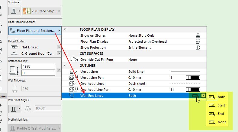
Check the end line setting within your
Ling.
Ling.
| AC22-29 AUS 3200 | Help Those Help You - Add a Signature |
| Self-taught, bend it till it breaks | Creating a Thread |
| Win11 | i9 10850K | 64GB | RX6600 | Win11 | 7800X3D | 32GB | RTX5070TI |
Anonymous
Not applicable
Options
- Mark as New
- Bookmark
- Subscribe
- Mute
- Subscribe to RSS Feed
- Permalink
- Report Inappropriate Content
2021-04-02 02:55 PM
2021-04-02
02:55 PM
Lingwisyer wrote:Thanks a lot Ling,
Check the end line setting within yourComposite. There are a couple of threads around regarding what I assume this is in regards to walls. The setting for slabs is identical.
Ling.
It worked smoothly. I still have a little problem that you may be able to help me.
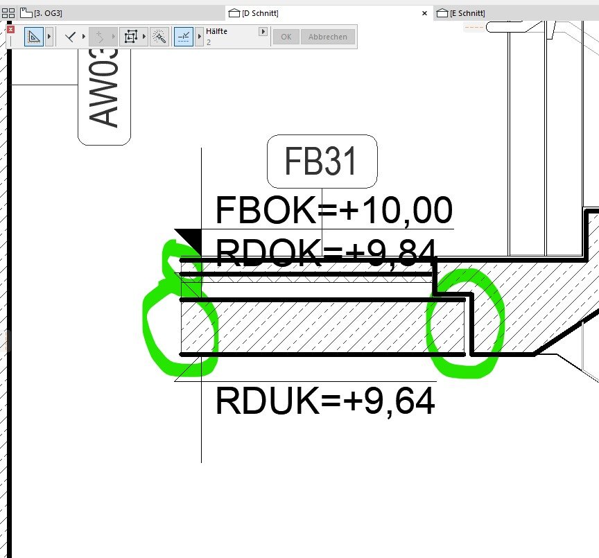
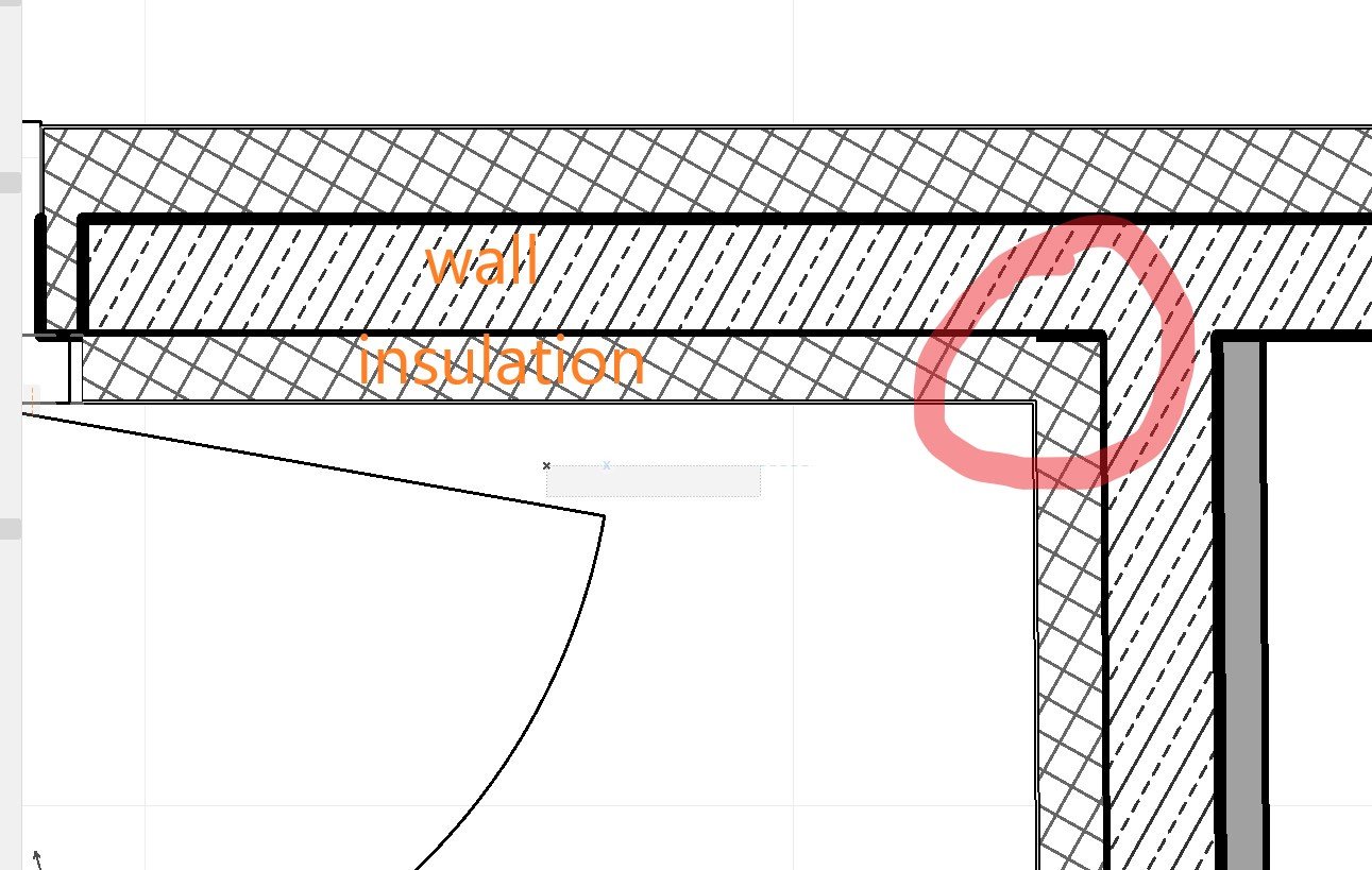
Attached you will find a couple of images. The corner of the insulation is having a thicker line and I have not been able to solve this problem.
Any clue?
Thanks a lot in advance
Sergio
Erwin Edel
Rockstar
Options
- Mark as New
- Bookmark
- Subscribe
- Mute
- Subscribe to RSS Feed
- Permalink
- Report Inappropriate Content
2021-04-06 09:45 AM
2021-04-06
09:45 AM
What you see in the floorplan is a scripted 2D representation. The problem is the script 'grabs' the pen settings from the part of the composite / complex profile wall that it touches.
This is a bit hard to fix, you would have to manipulate the script of the library part most likely.
In these instances I generally think 'this is as good as it will get, within reasonable amount of work spent' and move on.
That said: depending on the priority of the building material, you could place a column with the insulation material, instead of using the door / window settings to create this in plan and you might get better result. You would need to place a lot of columns (depending on the amount of doors) and move them whenever you move the door though.
Erwin Edel, Project Lead, Leloup Architecten
www.leloup.nl
ArchiCAD 9-29NED FULL
Windows 11 Pro for Workstations
Adobe Design Premium CS5
www.leloup.nl
ArchiCAD 9-29NED FULL
Windows 11 Pro for Workstations
Adobe Design Premium CS5
Anonymous
Not applicable
Options
- Mark as New
- Bookmark
- Subscribe
- Mute
- Subscribe to RSS Feed
- Permalink
- Report Inappropriate Content
2021-04-06 11:50 AM
2021-04-06
11:50 AM
Erwin wrote:Hi Erwin,
What you see in the floorplan is a scripted 2D representation. The problem is the script 'grabs' the pen settings from the part of the composite / complex profile wall that it touches.
This is a bit hard to fix, you would have to manipulate the script of the library part most likely.
In these instances I generally think 'this is as good as it will get, within reasonable amount of work spent' and move on.
That said: depending on the priority of the building material, you could place a column with the insulation material, instead of using the door / window settings to create this in plan and you might get better result. You would need to place a lot of columns (depending on the amount of doors) and move them whenever you move the door though.
Thanks for the info. I'd like to know where do I find the scripts for the composite? I think it would be a good idea to solve the problem once and for all and use it/share it so everyone of us can deal better with this problem. I am sure we all have had this question before.
Thnks in advance.
Cheers
Sergio
Anonymous
Not applicable
Options
- Mark as New
- Bookmark
- Subscribe
- Mute
- Subscribe to RSS Feed
- Permalink
- Report Inappropriate Content
2021-04-06 06:18 PM
2021-04-06
06:18 PM
Hello again,
and again with some hierarchical problems. These are two walls I did not draw. Still one is concrete and the other is the insulation. In any case the insulation appears to be on the top of the concrete one and this is exactly the opposite i want to see.
I have tried to send it to back but I think these commands are only working for 2d elements rather than 3d elements.
Is it possible to solve it somehow?
Thanks again in advance
Cheers
Sergio
runxel
Moderator
Options
- Mark as New
- Bookmark
- Subscribe
- Mute
- Subscribe to RSS Feed
- Permalink
- Report Inappropriate Content
2021-04-06 09:30 PM
2021-04-06
09:30 PM
Svorgodne wrote:It's in the script of the door/window. Prepare yourself for alot of trouble, because those are full with macros calls inside macro calls.... It would be definitely a very big task – even for the most proficient GDL coders out there.
I'd like to know where do I find the scripts for the composite? I think it would be a good idea to solve the problem once and for all and use it/share it so everyone of us can deal better with this problem. I am sure we all have had this question before.
Lucas Becker | AC 29 on Mac (Sequoia) | Graphisoft Insider Panelist | Akroter.io – high-end GDL objects | Author of Runxel's Archicad Wiki | Editor at SelfGDL | Developer of the GDL plugin for Sublime Text
My List of AC shortcomings & bugs | I Will Piledrive You If You Mention AI Again |
POSIWID – The Purpose Of a System Is What It Does /// «Furthermore, I consider that Carth... yearly releases must be destroyed»
My List of AC shortcomings & bugs | I Will Piledrive You If You Mention AI Again |
POSIWID – The Purpose Of a System Is What It Does /// «Furthermore, I consider that Carth... yearly releases must be destroyed»
Barry Kelly
Moderator
Options
- Mark as New
- Bookmark
- Subscribe
- Mute
- Subscribe to RSS Feed
- Permalink
- Report Inappropriate Content
2021-04-07 03:21 AM
2021-04-07
03:21 AM
Svorgodne wrote:
These are two walls I did not draw. Still one is concrete and the other is the insulation. In any case the insulation appears to be on the top of the concrete one and this is exactly the opposite i want to see.
Check the strength of the building materials used in the walls.
Stronger building materials will trim weaker ones - but I don't think that is the issue here.
Display order will affect the plan view of 3D elements - including walls.
So you should be able to send the insulation wall back or bring the other wall forward.
You will see the line along the joining length will belong to one or the other wall - depending which is on top in display order.
Currently your insulation wall is above the other wall in display order - hence the thinner joining line between the two walls.
The thick end line you have circled is because the insulation has no end lines at the moment.
If it is a composite wall, you can turn on the end lines in the composite settings dialogue.
If it is not a composite or that did not help, then in the floor plan display settings for the wall you can turn on the end lines (usually this is on by default).
Barry.
One of the forum moderators.
Versions 6.5 to 27
i7-10700 @ 2.9Ghz, 32GB ram, GeForce RTX 2060 (6GB), Windows 10
Lenovo Thinkpad - i7-1270P 2.20 GHz, 32GB RAM, Nvidia T550, Windows 11
Versions 6.5 to 27
i7-10700 @ 2.9Ghz, 32GB ram, GeForce RTX 2060 (6GB), Windows 10
Lenovo Thinkpad - i7-1270P 2.20 GHz, 32GB RAM, Nvidia T550, Windows 11
Graphisoft Alumni
Options
- Mark as New
- Bookmark
- Subscribe
- Mute
- Subscribe to RSS Feed
- Permalink
- Report Inappropriate Content
2021-04-09 09:41 AM
2021-04-09
09:41 AM
Svorgodne wrote:Hello Sergio,
Thanks a lot Ling,
It worked smoothly. I still have a little problem that you may be able to help me.
Attached you will find a couple of images. The corner of the insulation is having a thicker line and I have not been able to solve this problem.
Any clue?
Thanks a lot in advance
Sergio
Thank you very much for the report and I am very sorry about the issue!
Unfortunately, this was an old defect with the library part that has not been fixed, due to the low number of reports. It is registered in our system as DEF-4521. Sadly, there is no easy workaround for this problem. I reopened the case once again, hopefully, to give it a higher priority.
Regarding your second problem:
Svorgodne wrote:Am I correct to assume that the insulation is modeled using separate single-layer walls? When the reference lines of different walls touching each other, their presentation tends to be messy. But if these are 2 composite walls connecting in a T-shape manner, then please let me know!
and again with some hierarchical problems. These are two walls I did not draw. Still one is concrete and the other is the insulation. In any case the insulation appears to be on the top of the concrete one and this is exactly the opposite i want to see.
Best regards,
Minh
Minh Nguyen
Technical Support Engineer
GRAPHISOFT
Still looking?
Suggested topics
