
Turn on suggestions
Auto-suggest helps you quickly narrow down your search results by suggesting possible matches as you type.
Showing results for
EN
Turn on suggestions
Auto-suggest helps you quickly narrow down your search results by suggesting possible matches as you type.
Showing results for
Options
- Subscribe to RSS Feed
- Mark Topic as New
- Mark Topic as Read
- Pin this post for me
- Bookmark
- Subscribe to Topic
- Mute
- Printer Friendly Page
Anonymous
Not applicable
Options
- Mark as New
- Bookmark
- Subscribe
- Mute
- Subscribe to RSS Feed
- Permalink
- Report Inappropriate Content
2008-08-08 07:32 PM
Intersection and priorities in complex profiles
2008-08-08
07:32 PM
Do comlex profiles behave the same way as composite walls regarding skin priorities?
I made a little test profile just fot the sake of example, see the picture below.
-the reference lines are touching
-the brick skin priority is set to 0
-the brown skin priority is set to 6
And still, the skins are not intersecting properly at the "T" junction.
I searched the forums for a similar situation but couldnt find it.
Is there something I missed?

23 Replies 23
Karl Ottenstein
Moderator Emeritus
Options
- Mark as New
- Bookmark
- Subscribe
- Mute
- Subscribe to RSS Feed
- Permalink
- Report Inappropriate Content
2008-08-08 07:58 PM
2008-08-08
07:58 PM
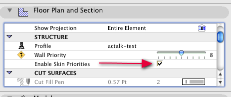
See attached screenshot: for the priorities that you set up in the profile to be considered, you must check the box for 'Enable Skin Priorities'.
(Generally, for composites and profiles, I have all boxes checked so that the composite or profile definition defines all attributes, thus making the definition a 'style' or 'type' that can be edited in one place and changed everywhere.)
Cheers,
Karl
(Generally, for composites and profiles, I have all boxes checked so that the composite or profile definition defines all attributes, thus making the definition a 'style' or 'type' that can be edited in one place and changed everywhere.)
Cheers,
Karl
Vote for Wish: Copy/Paste in 3D
AC 29 USA and earlier • hardware key • macOS Tahoe 26.5.2 MacBook Pro M2 Max 12CPU/30GPU cores, 32GB
AC 29 USA and earlier • hardware key • macOS Tahoe 26.5.2 MacBook Pro M2 Max 12CPU/30GPU cores, 32GB
Karl Ottenstein
Moderator Emeritus
Options
- Mark as New
- Bookmark
- Subscribe
- Mute
- Subscribe to RSS Feed
- Permalink
- Report Inappropriate Content
2008-08-08 08:04 PM
2008-08-08
08:04 PM
In the process of reproducing your screenshot, I discovered an unpleasant situation in 11 (have not tested in 12) regarding the 'Ending Contour' pen for the complex wall profile.
See the attached screenshot. The full ends show the heavy black line, but it also shows up as a short segment on one side of one skin of a wrapped corner. Pretty bizarre. Anybody have an idea on that one?
Cheers,
Karl

See the attached screenshot. The full ends show the heavy black line, but it also shows up as a short segment on one side of one skin of a wrapped corner. Pretty bizarre. Anybody have an idea on that one?
Cheers,
Karl
Vote for Wish: Copy/Paste in 3D
AC 29 USA and earlier • hardware key • macOS Tahoe 26.5.2 MacBook Pro M2 Max 12CPU/30GPU cores, 32GB
AC 29 USA and earlier • hardware key • macOS Tahoe 26.5.2 MacBook Pro M2 Max 12CPU/30GPU cores, 32GB
Karl Ottenstein
Moderator Emeritus
Options
- Mark as New
- Bookmark
- Subscribe
- Mute
- Subscribe to RSS Feed
- Permalink
- Report Inappropriate Content
2008-08-08 08:18 PM
2008-08-08
08:18 PM
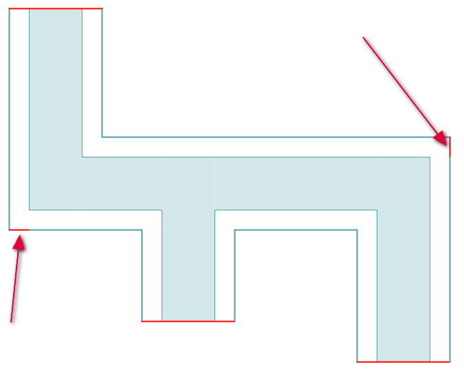
This gets weirder: in 12, the short end segments are still there, but on opposite sides of the corner. But, in 12, I cannot seem to control the weight of the contour cut by the floor plan cut plane.
No matter what pen I assign, the outside contour lines are always the same weight. The teal/blue pen is hairline (0 mm) and the red is 1.00 mm, but they appear the same in the attached screenshot. The pen color is clearly being taken from the Profile Editor, but I have no idea where the weight is coming from...?
Karl
Vote for Wish: Copy/Paste in 3D
AC 29 USA and earlier • hardware key • macOS Tahoe 26.5.2 MacBook Pro M2 Max 12CPU/30GPU cores, 32GB
AC 29 USA and earlier • hardware key • macOS Tahoe 26.5.2 MacBook Pro M2 Max 12CPU/30GPU cores, 32GB
Anonymous
Not applicable
Options
- Mark as New
- Bookmark
- Subscribe
- Mute
- Subscribe to RSS Feed
- Permalink
- Report Inappropriate Content
2008-08-08 08:33 PM
2008-08-08
08:33 PM
Thank you Karl for the quick reply.
I also had that box checked for my profiles ( in fact it the 1st thing I checked ). I suspect that you are using a "composite wall" rather than a "complex profile" (the later being accessed in the profile manager).
The quick example I posted might be what confused you.
in fact the mouldings are more like an extrusion.
here is a picture of how I worked my way around the problem. I used two half profiles with reference lines on the "outer edge" so they dont overlap.
top picture is the first unworking model, bottom one is the workaround.
Cheers!
EDIT: seems like we posted at the same time ( and I was wrong, you ARE using the complex profile after all)
And thats a weird behavior you have there with those endlines
Karl Ottenstein
Moderator Emeritus
Options
- Mark as New
- Bookmark
- Subscribe
- Mute
- Subscribe to RSS Feed
- Permalink
- Report Inappropriate Content
2008-08-08 10:05 PM
2008-08-08
10:05 PM
ArthurG wrote:I did not need any workaround to get the complex profile to intersect correctly. If your original profile is still not intersecting, select just those pieces and do a 'save selection as module' and post a zip of the module.
here is a picture of how I worked my way around the problem.
Cheers,
Karl
Vote for Wish: Copy/Paste in 3D
AC 29 USA and earlier • hardware key • macOS Tahoe 26.5.2 MacBook Pro M2 Max 12CPU/30GPU cores, 32GB
AC 29 USA and earlier • hardware key • macOS Tahoe 26.5.2 MacBook Pro M2 Max 12CPU/30GPU cores, 32GB
Anonymous
Not applicable
Options
- Mark as New
- Bookmark
- Subscribe
- Mute
- Subscribe to RSS Feed
- Permalink
- Report Inappropriate Content
2008-08-10 10:37 PM
2008-08-10
10:37 PM
Hello.
I have read this post a few times, but somehow don't think I'm getting it just yet.
Based on Arthur's last example, I may be trying to do something that is not possible in C.P. because the last 2d "workaround" looks different than what I'm after.
So attached is what I've been trying to do, and hopefully someone can let me know if it is even possible in C.P..
At least at that point, I will struggle on!
Bier
Karl Ottenstein
Moderator Emeritus
Options
- Mark as New
- Bookmark
- Subscribe
- Mute
- Subscribe to RSS Feed
- Permalink
- Report Inappropriate Content
2008-08-10 10:57 PM
2008-08-10
10:57 PM
There is no workaround, Bier. It just works - as seen in my screenshots.
In that case, I had a profile that had two tall 'curbs' on either side of a 'roadway'. I just repeated it with a new profile along the lines of your screenshot where you just circled the tops of the 'curbs' - suggesting a full slab below. With the 'roadway' at priority 6 and the 'curbs' at priority 0, the correct result is seen.
If you do not see all of the contours at all - then it is a Floor Plan Cut Plane height issue. If they intersect incorrectly, then make sure that the fills are different, the priorities are set similar to above, and that the tool settings are NOT over-riding any of the profile settings.😉
Cheers,
Karl
In that case, I had a profile that had two tall 'curbs' on either side of a 'roadway'. I just repeated it with a new profile along the lines of your screenshot where you just circled the tops of the 'curbs' - suggesting a full slab below. With the 'roadway' at priority 6 and the 'curbs' at priority 0, the correct result is seen.
If you do not see all of the contours at all - then it is a Floor Plan Cut Plane height issue. If they intersect incorrectly, then make sure that the fills are different, the priorities are set similar to above, and that the tool settings are NOT over-riding any of the profile settings.
Cheers,
Karl
Vote for Wish: Copy/Paste in 3D
AC 29 USA and earlier • hardware key • macOS Tahoe 26.5.2 MacBook Pro M2 Max 12CPU/30GPU cores, 32GB
AC 29 USA and earlier • hardware key • macOS Tahoe 26.5.2 MacBook Pro M2 Max 12CPU/30GPU cores, 32GB
Rod Jurich
Contributor
Options
- Mark as New
- Bookmark
- Subscribe
- Mute
- Subscribe to RSS Feed
- Permalink
- Report Inappropriate Content
2008-08-10 11:10 PM
2008-08-10
11:10 PM
Bier wrote:No need to struggle Bier, this may help.
Hello.
I have read this post a few times, but somehow don't think I'm getting it just yet.
/..........
At least at that point, I will struggle on!
Celia's Tip
Rod Jurich
AC4.55 - AC14 INT (4204) | | OBJECTiVE |
AC4.55 - AC14 INT (4204) | | OBJECTiVE |
Graphisoft Partner
Options
- Mark as New
- Bookmark
- Subscribe
- Mute
- Subscribe to RSS Feed
- Permalink
- Report Inappropriate Content
2008-08-11 01:12 AM
2008-08-11
01:12 AM
Karl wrote:Karl, are you assigning the Ending Contours in the Profile? Of course all the Structure's Settings must be applied in the Wall Settings.
No matter what pen I assign, the outside contour lines are always the same weight. The teal/blue pen is hairline (0 mm) and the red is 1.00 mm, but they appear the same in the attached screenshot. The pen color is clearly being taken from the Profile Editor, but I have no idea where the weight is coming from...?
Cheers,
Link.

Still looking?
Suggested topics
