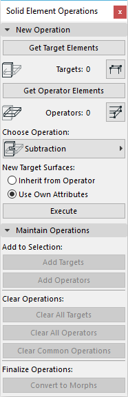
Design->Solid Element Operations performed on Zones
Elements’ Geometry affecting Zone Data
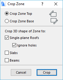
Zone 3D shape and behavior affected by Slanted Walls/Columns/Beams etc.
Position of Zone Reference Point
If you place the Zone Stamp with one of the automatic recognition methods, you will see a cross appear inside the Zone at the location that you first clicked to define the Zone’s area. This cross indicates the reference point of the Zone. This point is used as the starting point of boundary recognition for subsequent updating actions.
Global Setting affecting Zones’ View
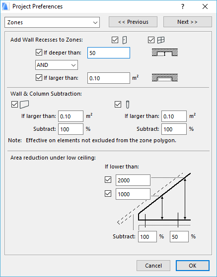
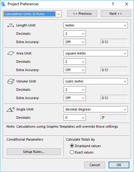
Options->Project Preferences->Dimensions/Calculation Units & Rules Dialog
Zone Stamp Library Parts and their parameters
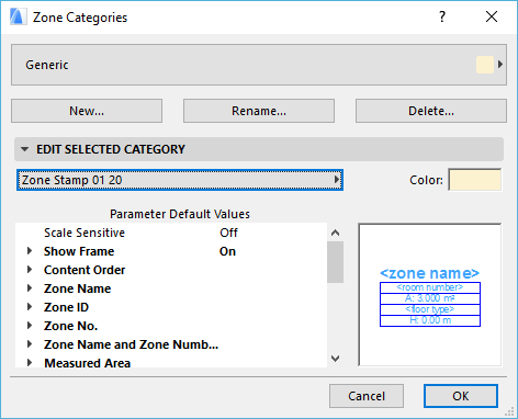
Options->Element Attributes->Zone Categories
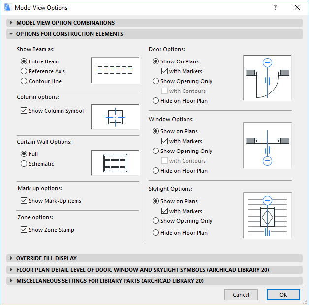
Document->Model View->Model View Options->Options for Construction Elements panel->Zone options->Show Zone Stamp checkbox
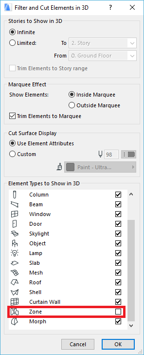
View->Elements in 3D View->Filter and Cut Elements in 3D Dialog->Element Types to Show in 3D field
Actions affecting Zones’ View
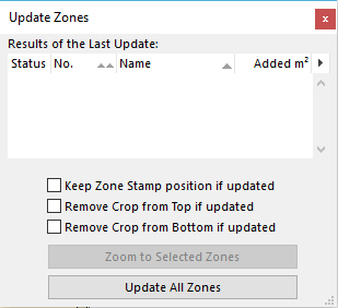
Design->Update Zones Dialog - Update of Zones depending on how GDL is written