Turn on suggestions
Auto-suggest helps you quickly narrow down your search results by suggesting possible matches as you type.
Showing results for
Turn on suggestions
Auto-suggest helps you quickly narrow down your search results by suggesting possible matches as you type.
Showing results for
- Graphisoft Community (INT)
- :
- Forum
- :
- Documentation
- :
- Shaded Elevations - how to achieve pure white? How...
Options
- Subscribe to RSS Feed
- Mark Topic as New
- Mark Topic as Read
- Pin this post for me
- Bookmark
- Subscribe to Topic
- Mute
- Printer Friendly Page
Documentation
About Archicad's documenting tools, views, model filtering, layouts, publishing, etc.
Shaded Elevations - how to achieve pure white? How to achieve solid+transparent areas within fills?
Options
- Mark as New
- Bookmark
- Subscribe
- Mute
- Subscribe to RSS Feed
- Permalink
- Report Inappropriate Content
2019-10-07
08:21 AM
- last edited on
2023-05-23
03:05 AM
by
![]() Gordana Radonic
Gordana Radonic
2019-10-07
08:21 AM
Also, has anyone come up with a cunning way that a cover fill for a perforated wall panel element can have a pattern of white masking areas alternating with transparent hole areas that are individually outlined with black pen? (as opposed to the outline of the fill as a whole)?
I can achieve this in 3D with alpha channel for transparency in surface texture, but cannot think of a way in 2D.
Really hoping to avoid physically modeling every perforation to achieve this, as there are thousands of holes, which will massively slow down the model.
PAUL KING | https://www.prime.net.nz
ArchiCAD 8-28 | Twinmotion 2024
Windoze 11 PC | Intel Core i9 10900K | Nvidia Gforce RTX 3080 | 32 Gb DDR3 | 2x4K monitor extended desktop
ArchiCAD 8-28 | Twinmotion 2024
Windoze 11 PC | Intel Core i9 10900K | Nvidia Gforce RTX 3080 | 32 Gb DDR3 | 2x4K monitor extended desktop
Labels:
- Labels:
-
Elevations
20 REPLIES 20
Options
- Mark as New
- Bookmark
- Subscribe
- Mute
- Subscribe to RSS Feed
- Permalink
- Report Inappropriate Content
2019-10-07 09:04 AM
2019-10-07
09:04 AM
In the elevation settings you will have to set the uncut surfaces to "Own surface colour (non-shaded)"
You can still have shadows on so you will get the shadows cast from other elements.
Barry.
You can still have shadows on so you will get the shadows cast from other elements.
Barry.
One of the forum moderators.
Versions 6.5 to 27
i7-10700 @ 2.9Ghz, 32GB ram, GeForce RTX 2060 (6GB), Windows 10
Lenovo Thinkpad - i7-1270P 2.20 GHz, 32GB RAM, Nvidia T550, Windows 11
Versions 6.5 to 27
i7-10700 @ 2.9Ghz, 32GB ram, GeForce RTX 2060 (6GB), Windows 10
Lenovo Thinkpad - i7-1270P 2.20 GHz, 32GB RAM, Nvidia T550, Windows 11
Options
- Mark as New
- Bookmark
- Subscribe
- Mute
- Subscribe to RSS Feed
- Permalink
- Report Inappropriate Content
2019-10-07 09:42 AM
2019-10-07
09:42 AM
Thanks Barry
That is what I currently have - but if I define the fill associated with the perforated surface to use using just lines for the fill pattern, the holes in perforated sheet surface are not transparent - I just see the linework over a solid background.
If I paste a solid fill with holes cut into it into the associated symbol fill definition dialog, this creates a solid black and white shaded appearance to that surface in elevation - again no transparency - even when transparency is switched on in shaded elevations.
PAUL KING | https://www.prime.net.nz
ArchiCAD 8-28 | Twinmotion 2024
Windoze 11 PC | Intel Core i9 10900K | Nvidia Gforce RTX 3080 | 32 Gb DDR3 | 2x4K monitor extended desktop
ArchiCAD 8-28 | Twinmotion 2024
Windoze 11 PC | Intel Core i9 10900K | Nvidia Gforce RTX 3080 | 32 Gb DDR3 | 2x4K monitor extended desktop
Options
- Mark as New
- Bookmark
- Subscribe
- Mute
- Subscribe to RSS Feed
- Permalink
- Report Inappropriate Content
2019-10-07 09:57 AM
2019-10-07
09:57 AM
I was only answering the first part of your question.
Can you show an image of what you are trying to do with the perforations?
A surface material can have transparency that will make the entire element transparent (like glass).
Or you can attach an image to your surface material that has an masking channel built into it but this only shows in OpenGL and CineRender.
The elevations only use the vectorial engine and not OpenGL.
Barry.
One of the forum moderators.
Versions 6.5 to 27
i7-10700 @ 2.9Ghz, 32GB ram, GeForce RTX 2060 (6GB), Windows 10
Lenovo Thinkpad - i7-1270P 2.20 GHz, 32GB RAM, Nvidia T550, Windows 11
Versions 6.5 to 27
i7-10700 @ 2.9Ghz, 32GB ram, GeForce RTX 2060 (6GB), Windows 10
Lenovo Thinkpad - i7-1270P 2.20 GHz, 32GB RAM, Nvidia T550, Windows 11
Options
- Mark as New
- Bookmark
- Subscribe
- Mute
- Subscribe to RSS Feed
- Permalink
- Report Inappropriate Content
2019-10-07 10:07 AM
2019-10-07
10:07 AM
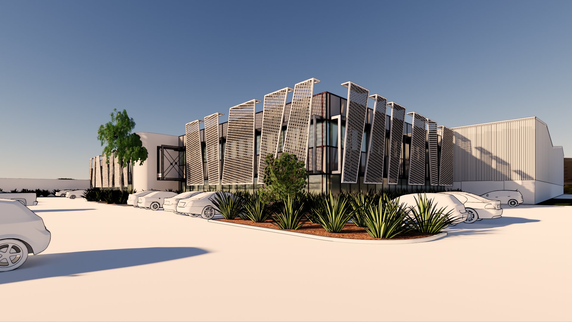
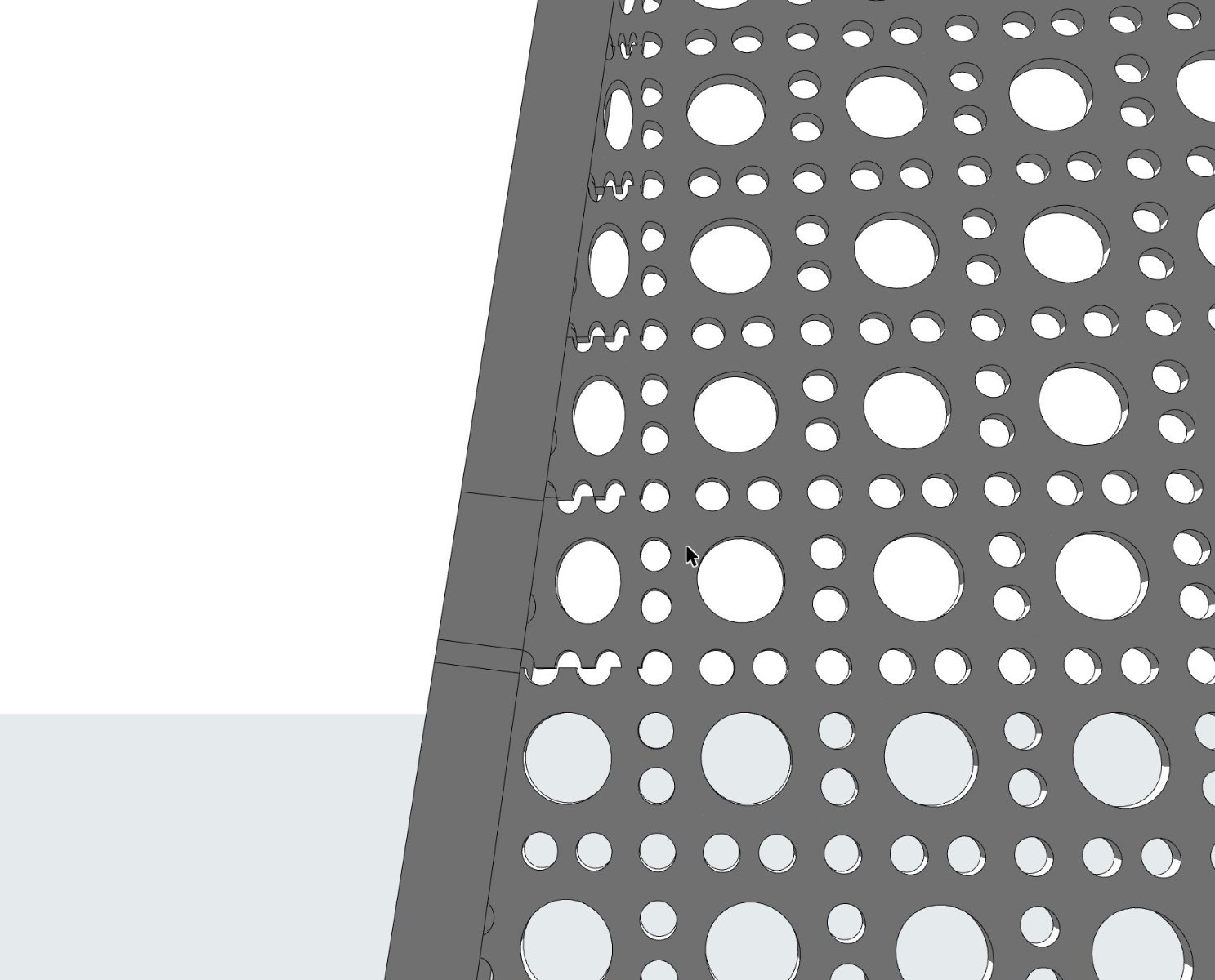
I have attached a 3D view to give some context, and a section of shaded elevation view.
I am basically trying to find out what sneaky things people do to depict perforated materials in shaded elevations.
I don't want to have to physically model the holes, or resort to rendered elevations if at all possible.
Because perforated sheet materials are so common these days, I am hoping someone has come up with an effective and efficient workaround for showing these in shaded views... Some way of creating a masking overlay with holes in all the right places perhaps.
PAUL KING | https://www.prime.net.nz
ArchiCAD 8-28 | Twinmotion 2024
Windoze 11 PC | Intel Core i9 10900K | Nvidia Gforce RTX 3080 | 32 Gb DDR3 | 2x4K monitor extended desktop
ArchiCAD 8-28 | Twinmotion 2024
Windoze 11 PC | Intel Core i9 10900K | Nvidia Gforce RTX 3080 | 32 Gb DDR3 | 2x4K monitor extended desktop
Options
- Mark as New
- Bookmark
- Subscribe
- Mute
- Subscribe to RSS Feed
- Permalink
- Report Inappropriate Content
2019-10-07 10:24 AM
2019-10-07
10:24 AM
Unless someone else does have a sneaky method, I am afraid it is going to be model the holes.
Even if you could use a transparent material, it would still appear solid in elevation unless you turn on transparency in the elevation settings.
Then all of the glass in your windows will also become transparent and you will see everything inside the building.
With regards to modelling, would the new curtain wall tool be a valid solution for the repeating holes.
I rarely use the curtain wall tool so don't really know without experimenting.
Barry.
One of the forum moderators.
Versions 6.5 to 27
i7-10700 @ 2.9Ghz, 32GB ram, GeForce RTX 2060 (6GB), Windows 10
Lenovo Thinkpad - i7-1270P 2.20 GHz, 32GB RAM, Nvidia T550, Windows 11
Versions 6.5 to 27
i7-10700 @ 2.9Ghz, 32GB ram, GeForce RTX 2060 (6GB), Windows 10
Lenovo Thinkpad - i7-1270P 2.20 GHz, 32GB RAM, Nvidia T550, Windows 11
Options
- Mark as New
- Bookmark
- Subscribe
- Mute
- Subscribe to RSS Feed
- Permalink
- Report Inappropriate Content
2019-10-07 12:17 PM
2019-10-07
12:17 PM
Thanks Barry
Curtain wall tool worth a look - never tried custom panels with random angled edges like this. May be a bit hard where panels fold over and become horizontal though.
Plan B would be to create a boolean cutter object that replicates to the repeating pattern, though lots of work required to constrain holes (and part holes) to a defined distance in from raking panel edges for all the panel shapes. Especially every time each panel shape and perforation pattern changes during design development.
Or plan C, just live with lack of transparent holes I guess..,.
PAUL KING | https://www.prime.net.nz
ArchiCAD 8-28 | Twinmotion 2024
Windoze 11 PC | Intel Core i9 10900K | Nvidia Gforce RTX 3080 | 32 Gb DDR3 | 2x4K monitor extended desktop
ArchiCAD 8-28 | Twinmotion 2024
Windoze 11 PC | Intel Core i9 10900K | Nvidia Gforce RTX 3080 | 32 Gb DDR3 | 2x4K monitor extended desktop
Options
- Mark as New
- Bookmark
- Subscribe
- Mute
- Subscribe to RSS Feed
- Permalink
- Report Inappropriate Content
2019-10-07 01:28 PM
2019-10-07
01:28 PM
Well curtain wall option may be a dead end - I can create a perforation pattern by making a scheme grid corresponding to perforation repeat distance each way - and using custom panel type defined using a slab with holes, and with invisible frame type of zero width between each panel.
Problem is that at the outer boundary edges of the curtain wall, the custom panels in affected edge locations distort to fit rather than allowing themselves to be cut to fit - this is true whether the boundary edge is orthogonal or angled.
Gets even worse if you rotate the scheme grid to anything non orthogonal.
Maybe a curtain wall guru out there knows a better way, or what setting I am missing to prevent panel distortion?
PAUL KING | https://www.prime.net.nz
ArchiCAD 8-28 | Twinmotion 2024
Windoze 11 PC | Intel Core i9 10900K | Nvidia Gforce RTX 3080 | 32 Gb DDR3 | 2x4K monitor extended desktop
ArchiCAD 8-28 | Twinmotion 2024
Windoze 11 PC | Intel Core i9 10900K | Nvidia Gforce RTX 3080 | 32 Gb DDR3 | 2x4K monitor extended desktop
Options
- Mark as New
- Bookmark
- Subscribe
- Mute
- Subscribe to RSS Feed
- Permalink
- Report Inappropriate Content
2019-10-07 02:30 PM
2019-10-07
02:30 PM
The cutoff for transparancy for surfaces is at 50%. If you set it at 49, glass won't be transparant in elevations, but you can still see through it in 3D.
This allows you to somewhat cheat with shades of transparancy.
I use a percentage fill for something like exterior glass railings where I might want to see what's behind them.
I'd model the panels as a slab on the floor plan, make a MOD with circular columns on a hidden SEO layer that I can copy around the grid as needed and save each panel as its own object.
Edit:
Regarding the 'colours' in elevations, this seems to be drawn from a fairly limited pallette of colours, you can change settings for internal engine all you like, but the shades are very limited, it seems. We never could get a light enough shade of 'white' either. We get better results with vectorial fills and graphic overrides if we want to add a bit of shading for clarity.
Erwin Edel, Project Lead, Leloup Architecten
www.leloup.nl
ArchiCAD 9-26NED FULL
Windows 10 Pro
Adobe Design Premium CS5
www.leloup.nl
ArchiCAD 9-26NED FULL
Windows 10 Pro
Adobe Design Premium CS5
Options
- Mark as New
- Bookmark
- Subscribe
- Mute
- Subscribe to RSS Feed
- Permalink
- Report Inappropriate Content
2019-10-07 05:43 PM
2019-10-07
05:43 PM
THanks Irwin
A good tip with transparency%
The individual modelling of panels & SEO was something I was trying hard to avoid, as they will evolve in shape and perforation style - but I my other options seem to be limited....
Fallback was to make a forest of columns as cutters and just keep dropping slab of different shapes and orientations on it to auto cut holes, space click perimeter edge beam /trimer and save result as morph or GDL object. - but once made, hard to stretch shapes or swap hole patterns in 20 different panels each time ...
PAUL KING | https://www.prime.net.nz
ArchiCAD 8-28 | Twinmotion 2024
Windoze 11 PC | Intel Core i9 10900K | Nvidia Gforce RTX 3080 | 32 Gb DDR3 | 2x4K monitor extended desktop
ArchiCAD 8-28 | Twinmotion 2024
Windoze 11 PC | Intel Core i9 10900K | Nvidia Gforce RTX 3080 | 32 Gb DDR3 | 2x4K monitor extended desktop

Related articles
Still looking?
