Turn on suggestions
Auto-suggest helps you quickly narrow down your search results by suggesting possible matches as you type.
Showing results for
Turn on suggestions
Auto-suggest helps you quickly narrow down your search results by suggesting possible matches as you type.
Showing results for
- Graphisoft Community (INT)
- :
- Developer Hub
- :
- GDL
- :
- Re: Biarc curve
Options
- Subscribe to RSS Feed
- Mark Topic as New
- Mark Topic as Read
- Pin this post for me
- Bookmark
- Subscribe to Topic
- Mute
- Printer Friendly Page
GDL
About building parametric objects with GDL.
Open Source GDL library project
Options
- Mark as New
- Bookmark
- Subscribe
- Mute
- Subscribe to RSS Feed
- Permalink
- Report Inappropriate Content
2021-05-29
11:46 PM
- last edited on
2021-09-14
09:10 AM
by
![]() Noemi Balogh
Noemi Balogh
2021-05-29
11:46 PM
Hi there,
After long thinking on this subject I would like to hit the new Open Source GDL programming project on this forum. The idea to involve GDL developers worldwide to start building new, independent, international, non-commercial library for all. GDL technology has very strong potential and that is very important part why ArchiCAD as a CAD and BIM system is so unique.
Please read the initial statements of this project:
1. The project is running under the GNU GPL licence. It is based on GDL technology, but not limited by it. Any further translations to different programming languages or use in different CAD systems apart of ArchiCAD are welcomed. Additional C++ programming to improve use of the library parts by making special Add-Ons are welcomed too.
2. Anyone, who is taking part of the project, doing it by their free will and free of charge just following the desire to make BIM world better. Donations, investments and grants for developers are discussible and acceptable.
3. The objects must follow all official GDL standards (like GDL white paper) and Graphisoft recommendations. For example - I like to use uppercase in my GDL script for commands (because GDL manual shows all of them in uppercase). But as soon as GS recommends to use lowercase - my opinion or preferences are not valid.
4. Developed library parts must use standard GS variables names to have full compatibility with standard libraries, distributed with official ArchiCAD releases. As well - to use standard GDL subtypes, as soon as introducing new one is not necessary.
5. All library elements must be compatible with Grasshopper - means that most of calculations (that usually happens in Parameter script) shall happens in Master Script, because Grasshopper is not reading Parameter script.
6. Completed library element must be uploaded to BIMcomponents.com web-site for free access of ArchiCAD users worldwide.
7. Any modification to the library part code must be reflected into the versions text file (or log file), provided with the library element.
8. Library part must be truly international - means that they must have multi-language support.
9. Library objects must be not manufacturer-oriented but building element class-oriented with manufacturer support. For example - instead of having ACO drain element - to have rainwater drain element with possibility to choose ACO from manufacturers list.
10. There is no discussions about leadership of the project. Everyone is equal and differs only by experience - strongest are supporting weakest. I will try to manage this project as long as I can, also I'm willing to open some of my personal developments, but I do not pretend to be head of the project (even if this is my idea).
11. Anyone can be involved into any stage of library part development - starting from conceptual graphical schemes and algorithms ending by writing and re-writing actual scripts.
12. Any object must have textual / graphical description how to use it and YouTube video. The links to the manual must be implemented into the object User Interface.
13. Each object must have User Interface.
14. Common global variables names as for example from Add-Ons or MVO objects - matter of community decisions and consultancy with Graphisoft. After the decision is made - this subject is not discussable without serious technical reason.
15. Every GDL object must be written on as lowest ArchiCAD/GDL version as possible - as soon as needed features allowed to use the version.
16. Developing of the new object is starting by introducing your ideas in the post plus hand-drawn (or CAD drawn) sketches and logical (drawn) schemes.
17. This is not PARAM-O project. PARAM-O can be used as a temporary tool, but because of nature of scripts, generated by program automatically, must be reviewed and rewritten by human to achieve better performance and smaller size of script.
Any comments are welcomed.
Labels:
- Labels:
-
Library (GDL)
89 REPLIES 89
Anonymous
Not applicable
Options
- Mark as New
- Bookmark
- Subscribe
- Mute
- Subscribe to RSS Feed
- Permalink
- Report Inappropriate Content
2021-06-12 01:29 PM
2021-06-12
01:29 PM
Hi SinceV6,
Thanks for your thoughts... Lots of good points that made me rethink the idea. And the link/thread you showed (Raised by Paul King) is a very good description of the need for a proper Road Tool.
 ). Then as you said I do the drill... Trace a Mesh on the surveyor points (
 )... But I also have to make
 . With new urbanization projects is the same process... I mark some key levels for crossroads and then the interpolations for smooth slopes. And finally draw the 2d sloping diagram that the Civil Engineer will use to make soil fills/excavations. But imagine if I have to change some key levels
  With this object, I could trace the few points on the surveyor dwg > Enter its heights > Indicate the interpolation method for each segment > Once the points were ok then I generate a txt file with the contours and axis points (I am pretty sure Put, Get and I/O operations can do the trick) > Finally, I create a Mesh with the "Place a Mesh with the txt file". After this, I could use the Railing tool with magic wand to apply curbs, etc with regular AC tools. With the advantage that I could schedule and quantify everything (That's why I think that adding curbs, manholes and other accessories is not a good idea).
But perhaps you are right... The work involved in this object is not justified, as there are better workflows to achieve the same goal.
Cheers,
Thanks for your thoughts... Lots of good points that made me rethink the idea. And the link/thread you showed (Raised by Paul King) is a very good description of the need for a proper Road Tool.
sinceV6 wrote:The purpose of this object, is to streamline the process that I manually do with Meshes. Usually the surveyor delivers a dwg file with very few point (Perhaps I have to put some pressure on him for a better service
I understand the wish, but not what it would solve,...
But perhaps you are right... The work involved in this object is not justified, as there are better workflows to achieve the same goal.
Cheers,
Options
- Mark as New
- Bookmark
- Subscribe
- Mute
- Subscribe to RSS Feed
- Permalink
- Report Inappropriate Content
2021-06-14 05:10 PM
2021-06-14
05:10 PM
Hi.
Thanks Braza.
I think we would need a real case scenario to evaluate how this could be achieved. Anything you could share?
Better topo tools are needed indeed, as they are part of the architectural workflow. I think urbanization projects are another whole thing to be dealt within AC.
Best regards.
Thanks Braza.
I think we would need a real case scenario to evaluate how this could be achieved. Anything you could share?
Braza wrote:If urbanization projects are a constant thing, I would turn to see if there are other tools tailored for the task that could fit into the workflow. A hammer can be used for a lot of things, even put in a screw if needed, but a screwdriver will do a better job in that case.
... With new urbanization projects is the same process...
Better topo tools are needed indeed, as they are part of the architectural workflow. I think urbanization projects are another whole thing to be dealt within AC.
Best regards.
Anonymous
Not applicable
Options
- Mark as New
- Bookmark
- Subscribe
- Mute
- Subscribe to RSS Feed
- Permalink
- Report Inappropriate Content
2021-06-14 07:38 PM
2021-06-14
07:38 PM
Actually I am not practicing Architecture for a considerable time, as I mostly work for a contractor as a site manager on small residential projects. But I recall facing this kind of pain when I worked as Architect on small/mid size urbanization projects (up to 50 lots). I agree there are better tools for this job. But, as in the MEP design, there are some situations where the dimension of the work and the budget of the project doesn't allow me to buy and learn a dedicated software.
Options
- Mark as New
- Bookmark
- Subscribe
- Mute
- Subscribe to RSS Feed
- Permalink
- Report Inappropriate Content
2021-06-18 11:15 AM
2021-06-18
11:15 AM
Hello there!
Just quick upload of an object, that can be useful. Biarc curve - arcs with common tangent. Can be used for further developments - for example for the roads.
Currently it's simple 2d element. It has maximum 11 nodes (10 segments). Each node is moveable on plan. If you overlay one node on another - it disappears. It also has editable hotspots to control radiuses of the segments.
Script is OK, but in some cases it gives me sharp edge connection - the main formula that calculates radiuses needs to be improved. GDL version 32 - ArchiCAD 17.
Cheers.
Options
- Mark as New
- Bookmark
- Subscribe
- Mute
- Subscribe to RSS Feed
- Permalink
- Report Inappropriate Content
2021-06-18 08:02 PM
Options
- Mark as New
- Bookmark
- Subscribe
- Mute
- Subscribe to RSS Feed
- Permalink
- Report Inappropriate Content
2021-06-19 12:24 AM
2021-06-19
12:24 AM
Last bug fixed...
From the script you can see how I name variables. I like to write the code, that it would be more understandable by human by giving 'real' names to variables. For example if it's a length parameter - I use 'coordinates' or 'length' or 'distance' or 'radius' - it's clear, that distanceBend is length parameter. If it's an angle, then variable name angleBend.
If it's integer - I use 'type' or 'number': numberNodes. If it's a string, then it could be 'name': nameFile, nameImage
Options
- Mark as New
- Bookmark
- Subscribe
- Mute
- Subscribe to RSS Feed
- Permalink
- Report Inappropriate Content
2021-06-19 10:20 AM
2021-06-19
10:20 AM
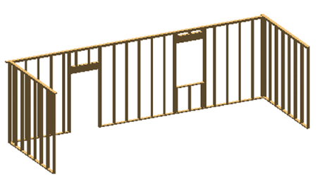
What about ameliorations of the existing framing object, it already works but with a llt of bugs and missi g good functuonnalities
- offset framing from wall edge (automatic or manual)
- making possible to add complex profiles to frames
- windows and doors special framing
- corner framing
- T junction framing
- offset framing from wall edge (automatic or manual)
- making possible to add complex profiles to frames
- windows and doors special framing
- corner framing
- T junction framing
AMD Ryzen 9 3900X, 32 GB RAM, RTX 3080 10 GB
Archicad 27
Windows 11 professional
https://www.behance.net/Nuance-Architects
Archicad 27
Windows 11 professional
https://www.behance.net/Nuance-Architects
Anonymous
Not applicable
Options
- Mark as New
- Bookmark
- Subscribe
- Mute
- Subscribe to RSS Feed
- Permalink
- Report Inappropriate Content
2021-06-19 12:39 PM
2021-06-19
12:39 PM
@Podolsky
Very cool object. I just think its usability is very limited. The 3d dynamic Polyline from SinceV6 is very versatile. This also makes me think which is the best way to trace road paths? Just Lines and Arcs? Quadratic Belsier curve? It would be nice if someone with Civil Engineering in this matter could put some light on it. I personally think Lines and Arcs can do the job.
@bouhmidage
This framing object uses the Wall Accessories Goodies, right?
If so, the problem is that it has little to no support from GS.
Besides this, I have seen many users using the Curtain Wall Element to do this with very good results. Including scheduling and quantities takeoffs.
p.s.: It would be really nice if SinceV6 could send us a simple object with a "raw/clean" working version of his 3d Polyline that we could start to work.
Options
- Mark as New
- Bookmark
- Subscribe
- Mute
- Subscribe to RSS Feed
- Permalink
- Report Inappropriate Content
2021-06-19 01:02 PM
2021-06-19
01:02 PM
The use of biarc is very important in architecture. As I know, in most cases it's biarcs instead of spline. As I know from people, who worked in road design - they never use splines. I uploaded the object on purpose - to use it as it is of course is limited, but it's can be useful for more complicated objects (as macro) to define let say edge of polygon. Also this algorithm can be converted into 3D curve - with some modifications. For example for plastic pipes, like MDPE or PEX. Standard set of MEP tools has only straight and curve parts, that needs to be combined together. That works for metal pipes - where bends are welded to straight parts, but when it's plastic - it usually goes as one long pipe up to 200 m. To have one long pipe that can be bended into any direction will solve this problem - for water supply or underfloor heating installations. Why this is important - to get right quantities. When I'm using standard parts (straight parts and bends) I'm getting very long schedule of lengths of all parts, that represents only one pipe. This is not comfortable.
Timber frames - it's something that I'm working on right now. Currently I'm finalising timber beam object (that has biarc curve as an option - this is from where this algorithm came). Next step will be floor joists and wall frames. Very possible that I will open my scripts for use for everyone, at least part of them for sure.
Timber frames - it's something that I'm working on right now. Currently I'm finalising timber beam object (that has biarc curve as an option - this is from where this algorithm came). Next step will be floor joists and wall frames. Very possible that I will open my scripts for use for everyone, at least part of them for sure.
Options
- Mark as New
- Bookmark
- Subscribe
- Mute
- Subscribe to RSS Feed
- Permalink
- Report Inappropriate Content
2021-06-19 01:25 PM
2021-06-19
01:25 PM
I also want to say, that I don't think that to use curtain wall for something else apart of curtain wall - like for concrete blocks or timber frame or railing for curb stone is a good idea. ArchiCAD is based on objects (as principle of object-oriented programming) and each object represents specific element. It remains me conversations happened long time ago about difference between modelling in 3DS Max and ArchiCAD. I did hear a lot of critics towards ArchiCAD - that to compare to Max ArchiCAD is limited in modelling. But there is the whole point - building elements and building materials are limited in use and their geometry fits to specific, limited again, needs - you cannot use bricks for roof tiles, windows for rooflights or reinforced concrete for furniture.
Making GDL objects, that serve specific needs (like wall frames), instead of making universal objects - for example the same frame, that you can use and for wall and for floor and for roof, will give better results in the projects, because each building structure has its own special features, structural function and properties. Steel connections are different for slab and wall - so, if include steel connections into timber frames (let say Simpsons Strong Tie) - it would be just great for making BIM models to LOD 5 and this is what construction sites are expecting from BIM.
Making GDL objects, that serve specific needs (like wall frames), instead of making universal objects - for example the same frame, that you can use and for wall and for floor and for roof, will give better results in the projects, because each building structure has its own special features, structural function and properties. Steel connections are different for slab and wall - so, if include steel connections into timber frames (let say Simpsons Strong Tie) - it would be just great for making BIM models to LOD 5 and this is what construction sites are expecting from BIM.
Suggested content
- Curved Sweep End Angle Not Exactly 90 degrees To Sweep Start Angle in GDL
- CMake and subdirectories in Archicad C++ API
- How to obtain the X and Y coordinates of vertices on curves or line segments in GDL programming in GDL
- Call Archicad Wall command from own dialog in Archicad C++ API
- Curved Wall Parameters for Labels and Column Section for Labels in GDL
Didn't find the answer?
Check other topics in this Forum
Back to ForumRead the latest accepted solutions!
Accepted SolutionsStart a new conversation!
