
Turn on suggestions
Auto-suggest helps you quickly narrow down your search results by suggesting possible matches as you type.
Showing results for
EN
Turn on suggestions
Auto-suggest helps you quickly narrow down your search results by suggesting possible matches as you type.
Showing results for
- English
- :
- Forum
- :
- Libraries & objects
- :
- how to create a fill section for a (morph) object
Options
- Subscribe to RSS Feed
- Mark Topic as New
- Mark Topic as Read
- Pin this post for me
- Bookmark
- Subscribe to Topic
- Mute
- Printer Friendly Page
Anonymous
Not applicable
Options
- Mark as New
- Bookmark
- Subscribe
- Mute
- Subscribe to RSS Feed
- Permalink
- Report Inappropriate Content
2017-04-14 08:28 PM
how to create a fill section for a (morph) object
2017-04-14
08:28 PM
i created an object through use of gdl, and used the definition of a morph to define it. Now i would like to add a section fill to the object. However this seems to be impossible (the morph is defined by verts/edges/polygons and doesn't contain a mass). When using the SECT_ATTRS command it won't show anything.
In an attempt to "solve" this i thought of using the MODEL SOLID command first before using the SECT_ATTRS, but without success.
So my question is: is it possible to transform the morph to a solid object and give it a section fill?
or is this impossible to do and i'll have to redefine the whole object using primitives
thank you
16 Replies 16
Bruce
Advisor
Options
- Mark as New
- Bookmark
- Subscribe
- Mute
- Subscribe to RSS Feed
- Permalink
- Report Inappropriate Content
2017-04-15 12:42 AM
2017-04-15
12:42 AM
It is possible. Near the beginning of the script created by ARCHICAD is a "sect_attr" command. This is where the cut fill is set.
You will also find a "material" and "pen" command too. Be aware that the material and pen are set further down the script as well. If your morph only has the one pen and material, you can get rid of these other commands, and just keep the material and pen settings at the beginning.
You will also find a "material" and "pen" command too. Be aware that the material and pen are set further down the script as well. If your morph only has the one pen and material, you can get rid of these other commands, and just keep the material and pen settings at the beginning.
Bruce Walker
Barking Dog BIM YouTube
Mindmeister Mindmap
-- since v8.1 --
AC27 5060 INT Full | Windows 11 64 Pro | 12th Gen Intel i7-12700H 2.30 GHz | 64 Gb RAM | NVIDIA GeForce RTX 3060 32 Gb
Barking Dog BIM YouTube
Mindmeister Mindmap
-- since v8.1 --
AC27 5060 INT Full | Windows 11 64 Pro | 12th Gen Intel i7-12700H 2.30 GHz | 64 Gb RAM | NVIDIA GeForce RTX 3060 32 Gb
Ruben V
Advocate
Options
- Mark as New
- Bookmark
- Subscribe
- Mute
- Subscribe to RSS Feed
- Permalink
- Report Inappropriate Content
2017-04-17 09:38 PM
2017-04-17
09:38 PM
Does the Morph, used for the GDL-object have to be 'solid' to achieve this?
Bruce
Advisor
Options
- Mark as New
- Bookmark
- Subscribe
- Mute
- Subscribe to RSS Feed
- Permalink
- Report Inappropriate Content
2017-04-17 10:21 PM
2017-04-17
10:21 PM
The material and pen settings will still work, but if an object is not solid, by definition, it will have no section fill. So yes, the morph needs to be solid.
Bruce Walker
Barking Dog BIM YouTube
Mindmeister Mindmap
-- since v8.1 --
AC27 5060 INT Full | Windows 11 64 Pro | 12th Gen Intel i7-12700H 2.30 GHz | 64 Gb RAM | NVIDIA GeForce RTX 3060 32 Gb
Barking Dog BIM YouTube
Mindmeister Mindmap
-- since v8.1 --
AC27 5060 INT Full | Windows 11 64 Pro | 12th Gen Intel i7-12700H 2.30 GHz | 64 Gb RAM | NVIDIA GeForce RTX 3060 32 Gb
Ruben V
Advocate
Options
- Mark as New
- Bookmark
- Subscribe
- Mute
- Subscribe to RSS Feed
- Permalink
- Report Inappropriate Content
2017-04-18 12:37 AM
2017-04-18
12:37 AM
How do you mean "by definition"?
If you leave out a the definition for one of the six faces of a cube, it won't be solid, but what if you've defined a pyramid-like form, with multiple (layered) materials, and al faces show properly in 3D, how can this 'become' non-solid?
What happens in my case is that when starting with any morph for a GDL-object, everything is fine. Combining multiple morphs and/or substituting multiple values with variables? Things start going wrong in the field of fills...
Bruce
Advisor
Options
- Mark as New
- Bookmark
- Subscribe
- Mute
- Subscribe to RSS Feed
- Permalink
- Report Inappropriate Content
2017-04-18 01:29 AM
2017-04-18
01:29 AM
'by definition' is just a turn of phrase - not a coding expression.
I don't know how you're trying to combine multiple morphs. If it was me, I would either:
1. If the separate morphs are to all be joined in the final geometry, then use boolean operations, and check morph solidity, prior to converting to GDL.
2. If separate geometries, then I would save them as separate GDL objects, each one called by the main object script.
I would use a CALL from the main object in any case, as it keeps the code cleaner.
Bruce Walker
Barking Dog BIM YouTube
Mindmeister Mindmap
-- since v8.1 --
AC27 5060 INT Full | Windows 11 64 Pro | 12th Gen Intel i7-12700H 2.30 GHz | 64 Gb RAM | NVIDIA GeForce RTX 3060 32 Gb
Barking Dog BIM YouTube
Mindmeister Mindmap
-- since v8.1 --
AC27 5060 INT Full | Windows 11 64 Pro | 12th Gen Intel i7-12700H 2.30 GHz | 64 Gb RAM | NVIDIA GeForce RTX 3060 32 Gb
Options
- Mark as New
- Bookmark
- Subscribe
- Mute
- Subscribe to RSS Feed
- Permalink
- Report Inappropriate Content
2017-04-18 09:34 AM
2017-04-18
09:34 AM
Regarding morphs to GDL:
Create the final geometry (-ies if more of morphs)
As Bruce said (clean, solidity check and so on)
move the geometry to the base point as desired....
now tricky:
right click and create morph from selection
and reset textures
(those avoid the unneeded translations in the final script)
if more morphs and not wiling to separate - ID all parts so to find them in the generated script.
Save to gdl...now You can remove the all translations and del's to optimize the script...of course do jumps etc to get it cleaner.
(remove XXXe-YYY...if possible to speedup)
Best Regards,
Piotr
Ruben V
Advocate
Options
- Mark as New
- Bookmark
- Subscribe
- Mute
- Subscribe to RSS Feed
- Permalink
- Report Inappropriate Content
2017-04-18 01:14 PM
2017-04-18
01:14 PM
thanks for this clear overview!
Ruben V
Advocate
Options
- Mark as New
- Bookmark
- Subscribe
- Mute
- Subscribe to RSS Feed
- Permalink
- Report Inappropriate Content
2017-05-18 11:34 AM
2017-05-18
11:34 AM
Still working on this problem...
Actually created a complex form using VERTS, EDGES and PGONS...
Seems to me that only primitives and PRISMS behave well regarding the 'solid 3D' and section Fill issue...
What am I missing? Should it also be fully scripted in 2D or should a standard PROJECT2 suffice?

Actually created a complex form using VERTS, EDGES and PGONS...
Seems to me that only primitives and PRISMS behave well regarding the 'solid 3D' and section Fill issue...
! TEST-script

model Solid

Material choose_surf
FILL hatch
sect_fill hatch,19,101,1

GOSUB 100
GOSUB 200


END

100:

Group "slab1"

base

! VERTS----------------

!ground plain
VERT 0,0,0					!#1
VERT 1,0,0					!#2
VERT 1,1,0					!#3
VERT 0,1,0					!#4

!vertical plains
vert 0,0,0					!#5
vert 1,0,0					!#6
vert 1,0,0.5				!#7
vert 0,0,0.5				!#8

vert 1,0,0					!#9
vert 1,1,0					!#10
vert 1,1,0.5				!#11
vert 1,0,0.5				!#12

vert 1,1,0					!#13
vert 0,1,0					!#14
vert 0,1,0.5				!#15
vert 1,1,0.5				!#16

vert 0,1,0					!#17
vert 0,0,0					!#18
vert 0,0,0.5				!#19
vert 0,1,0.5				!#20

!intermediate plain
VERT 0,0,0.5				!#21
VERT 1,0,0.5				!#22
VERT 1,1,0.5				!#23
VERT 0,1,0.5				!#24

!EDGES-----------------

!ground plain
EDGE 1,2,-1,-1,0			!#1
EDGE 2,3,-1,-1,0			!#2
EDGE 3,4,-1,-1,0			!#3
EDGE 4,1,-1,-1,0			!#4

!vertical edges
EDGE 5,6,-1,-1,0			!#5
EDGE 6,7,-1,-1,0			!#6
EDGE 7,8,-1,-1,0			!#7
EDGE 8,5,-1,-1,0			!#8

EDGE 9,10,-1,-1,0			!#9
EDGE 10,11,-1,-1,0			!#10
EDGE 11,12,-1,-1,0			!#11
EDGE 12,9,-1,-1,0			!#12

EDGE 13,14,-1,-1,0			!#13
EDGE 14,15,-1,-1,0			!#14
EDGE 15,16,-1,-1,0			!#15
EDGE 16,13,-1,-1,0			!#16

EDGE 17,18,-1,-1,0			!#17
EDGE 18,19,-1,-1,0			!#18
EDGE 19,20,-1,-1,0			!#19
EDGE 20,17,-1,-1,0			!#20

!intermediate plain
EDGE 21,22,-1,-1,0			!#21
EDGE 22,23,-1,-1,0			!#22
EDGE 23,24,-1,-1,0			!#23
EDGE 24,21,-1,-1,0			!#24

!PGONS------------------

!ground plain
PGON 4,0,-1,1,2,3,4

!vertical plains
PGON 4,0,-1,5,6,7,8
PGON 4,0,-1,9,10,11,12
PGON 4,0,-1,13,14,15,16
PGON 4,0,-1,17,18,19,20

!intermediate plain
PGON 4,0,-1,21,22,23,24


endgroup

placegroup "slab1"

return

200:
Group "slab2"

base

! VERTS----------------

!intermediate plain (overlapping)
VERT 0,0,0.5					!#1
VERT 1,0,0.5					!#2
VERT 1,1,0.5					!#3
VERT 0,1,0.5					!#4

!vertical plains
vert 0,0,0.5					!#5
vert 1,0,0.5					!#6
vert 1,0,1						!#7
vert 0,0,1						!#8

vert 1,0,0.5					!#9
vert 1,1,0.5					!#10
vert 1,1,1						!#11
vert 1,0,1						!#12

vert 1,1,0.5					!#13
vert 0,1,0.5					!#14
vert 0,1,1						!#15
vert 1,1,1						!#16

vert 0,1,0.5					!#17
vert 0,0,0.5					!#18
vert 0,0,1						!#19
vert 0,1,1						!#20

!top plain
VERT 0,0,1						!#21
VERT 1,0,1						!#22
VERT 1,1,1						!#23
VERT 0,1,1						!#24

!EDGES-----------------

!intermediate plain (overlapping)
EDGE 1,2,-1,-1,0			!#1
EDGE 2,3,-1,-1,0			!#2
EDGE 3,4,-1,-1,0			!#3
EDGE 4,1,-1,-1,0			!#4

!vertical edges
EDGE 5,6,-1,-1,0			!#5
EDGE 6,7,-1,-1,0			!#6
EDGE 7,8,-1,-1,0			!#7
EDGE 8,5,-1,-1,0			!#8

EDGE 9,10,-1,-1,0			!#9
EDGE 10,11,-1,-1,0			!#10
EDGE 11,12,-1,-1,0			!#11
EDGE 12,9,-1,-1,0			!#12

EDGE 13,14,-1,-1,0			!#13
EDGE 14,15,-1,-1,0			!#14
EDGE 15,16,-1,-1,0			!#15
EDGE 16,13,-1,-1,0			!#16

EDGE 17,18,-1,-1,0			!#17
EDGE 18,19,-1,-1,0			!#18
EDGE 19,20,-1,-1,0			!#19
EDGE 20,17,-1,-1,0			!#20

!top plain
EDGE 21,22,-1,-1,0			!#21
EDGE 22,23,-1,-1,0			!#22
EDGE 23,24,-1,-1,0			!#23
EDGE 24,21,-1,-1,0			!#24

!PGONS------------------

!intermediate plain (overlapping)
PGON 4,0,-1,1,2,3,4

!vertical plains
PGON 4,0,-1,5,6,7,8
PGON 4,0,-1,9,10,11,12
PGON 4,0,-1,13,14,15,16
PGON 4,0,-1,17,18,19,20

!top plain
PGON 4,0,-1,21,22,23,24


endgroup

placegroup "slab2"

return
this gives a 'non solid' object without a 2D fill in the section view...
What am I missing? Should it also be fully scripted in 2D or should a standard PROJECT2 suffice?
Ruben V
Advocate
Options
- Mark as New
- Bookmark
- Subscribe
- Mute
- Subscribe to RSS Feed
- Permalink
- Report Inappropriate Content
2017-05-18 11:35 AM
2017-05-18
11:35 AM
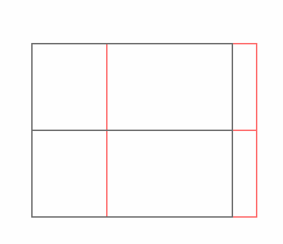
2D view (section)
Didn't find the answer?
Check other topics in this Forum
Back to ForumRead the latest accepted solutions!
Accepted SolutionsStart a new conversation!
Suggested topics
- Drafting aid object for geometry layouts in Modeling
- No-GDL Easy Parametric Object Creation in Libraries & objects
- Profile Stack 2D Detail object in Libraries & objects
- Creating Working Drawing Sections in Documentation
- Light Fixtures - Replacing the default 3d model of the fixture with a custom object in Libraries & objects
