
Turn on suggestions
Auto-suggest helps you quickly narrow down your search results by suggesting possible matches as you type.
Showing results for
EN
Turn on suggestions
Auto-suggest helps you quickly narrow down your search results by suggesting possible matches as you type.
Showing results for
Options
- Subscribe to RSS Feed
- Mark Topic as New
- Mark Topic as Read
- Pin this post for me
- Bookmark
- Subscribe to Topic
- Mute
- Printer Friendly Page
Anonymous
Not applicable
Options
- Mark as New
- Bookmark
- Subscribe
- Mute
- Subscribe to RSS Feed
- Permalink
- Report Inappropriate Content
2009-06-30 05:32 PM
Sections - what's your approach?
2009-06-30
05:32 PM
34 Replies 34
Thomas Holm
Enthusiast
Options
- Mark as New
- Bookmark
- Subscribe
- Mute
- Subscribe to RSS Feed
- Permalink
- Report Inappropriate Content
2009-06-30 06:18 PM
2009-06-30
06:18 PM
Depends on how you use the model. The more sections you want to cut, the more benefit from a detailed model. One section, no re-use, then you might as well draw it by hand 😉
AC4.1-AC26SWE; MacOS13.5.1; MP5,1+MBP16,1
Anonymous
Not applicable
Options
- Mark as New
- Bookmark
- Subscribe
- Mute
- Subscribe to RSS Feed
- Permalink
- Report Inappropriate Content
2009-06-30 08:36 PM
2009-06-30
08:36 PM
I have found that the more I model in 3d, the faster/more efficient my sectioning & detailing has become.
If, for example I add a subfloor slab of the proper thickness & section materials, all of my sections look the same, as do all of my details.
Visually everything looks better, and no matter where I need a detail, that part looks the same and it in the correct relationship with the other parts. Since the lion's share of my job is really structural design, it helps me troubleshoot everything that goes into a building, which of course makes me look really good to the builder. 3d makes my life easier all around!
Anonymous
Not applicable
Options
- Mark as New
- Bookmark
- Subscribe
- Mute
- Subscribe to RSS Feed
- Permalink
- Report Inappropriate Content
2009-07-01 02:14 PM
2009-07-01
02:14 PM
How do you go about adding lineweights? For example, what about the classic convention of having darker lines where air touches the building envelope? How do you achieve this?
It seems to me that by going all 3D, you would lose a lot of these conventions that make drawings look good. Do you model a drip edge on a house? Do you add rebar to the foundation walls? I guess I'm just a little skeptical because in 2D you can make something look perfect... I think I need to see a nice 3D section. Any volunteers?
It seems to me that by going all 3D, you would lose a lot of these conventions that make drawings look good. Do you model a drip edge on a house? Do you add rebar to the foundation walls? I guess I'm just a little skeptical because in 2D you can make something look perfect... I think I need to see a nice 3D section. Any volunteers?
Anonymous
Not applicable
Options
- Mark as New
- Bookmark
- Subscribe
- Mute
- Subscribe to RSS Feed
- Permalink
- Report Inappropriate Content
2009-07-01 03:41 PM
2009-07-01
03:41 PM
1. Create section with uniform pen for cut elements( heavy lineweight)
And uniform pen for uncut elements (lightest lineweight) and vectorial 3d hatching)
2. On the generated section draw over the generated element you want to stand out with intermediate lineweight lines or fills . Be sure to use a different layer for this embelishment work in case you need to erase or coordinate with the underlaying generated drawing.
Anonymous
Not applicable
Options
- Mark as New
- Bookmark
- Subscribe
- Mute
- Subscribe to RSS Feed
- Permalink
- Report Inappropriate Content
2009-07-01 03:44 PM
2009-07-01
03:44 PM
Ok, so you use the model but also 2D lines over the model to get it to look right? I was thinking everything is done in 3D.
Anonymous
Not applicable
Options
- Mark as New
- Bookmark
- Subscribe
- Mute
- Subscribe to RSS Feed
- Permalink
- Report Inappropriate Content
2009-07-01 04:39 PM
2009-07-01
04:39 PM
What about the 2x top, bottom & sill plates, & rim joist?
One way would be to create a custom profile for the foundation, which would include the concrete (w/ rebar) the sill plate (w/ anchor bolt) sill plate & rim joist and apply it. You could easily update it as you get structural info (fnd'n dimensions etc.) I suppose you could even include a sole plate in the profile.
You could do the same sort of thing at roofs & intermediate floors - profile that would include rim, sole & top plates. Is this workable?
jocontreras wrote:Too bad that Archicad can't do that automatically.
1. Create section with uniform pen for cut elements( heavy lineweight)
And uniform pen for uncut elements (lightest lineweight) and vectorial 3d hatching)
2. On the generated section draw over the generated element you want to stand out with intermediate lineweight lines or fills . Be sure to use a different layer for this embelishment work in case you need to erase or coordinate with the underlaying generated drawing.
Anonymous
Not applicable
Options
- Mark as New
- Bookmark
- Subscribe
- Mute
- Subscribe to RSS Feed
- Permalink
- Report Inappropriate Content
2009-07-01 05:34 PM
2009-07-01
05:34 PM
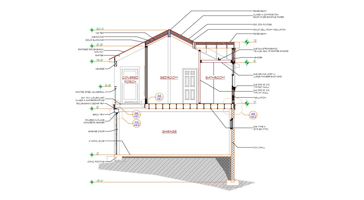
I am always in the process of developing my 3d modeling, and I like the idea of creating custom profiles, especially if more of my work was on projects that were alike. Unfortunately I can't justify the time to do that for each project and I end up detailing the sections and details using the Detailer Library for plates, rebar, bolts, etc.
We don't follow all of the normal conventions, but here's a section built with 3d slabs, walls, roofs, joists, and rafters (I love the Roof Wizard), then detailed out in 2d. Again, my focus is on solving any problems the builder may run into, but I love a pretty detail as much as the next guy.
We don't follow all of the normal conventions, but here's a section built with 3d slabs, walls, roofs, joists, and rafters (I love the Roof Wizard), then detailed out in 2d. Again, my focus is on solving any problems the builder may run into, but I love a pretty detail as much as the next guy.
Anonymous
Not applicable
Options
- Mark as New
- Bookmark
- Subscribe
- Mute
- Subscribe to RSS Feed
- Permalink
- Report Inappropriate Content
2009-07-01 05:49 PM
2009-07-01
05:49 PM
Looks good, but I don't know if the graphics would "fly" with the computer illiterate principals here...
Anonymous
Not applicable
Options
- Mark as New
- Bookmark
- Subscribe
- Mute
- Subscribe to RSS Feed
- Permalink
- Report Inappropriate Content
2009-07-01 06:00 PM
2009-07-01
06:00 PM
Do you have a sample of what does fly?
Still looking?
Suggested topics
- BEP hosting/sharing/coordination in Collaboration with other software
- How to model curved vertical wood slat wall paneling + fluted glass wall. Efficient workflow? in Modeling
- Section Markers do not match what is set up in Documentation
- What do you model in 3D and what do you detail in 2D? in Documentation
- What is the thick black line on the cross section of the door? in Libraries & objects
