
Turn on suggestions
Auto-suggest helps you quickly narrow down your search results by suggesting possible matches as you type.
Showing results for
EN
Turn on suggestions
Auto-suggest helps you quickly narrow down your search results by suggesting possible matches as you type.
Showing results for
Options
- Subscribe to RSS Feed
- Mark Topic as New
- Mark Topic as Read
- Pin this post for me
- Bookmark
- Subscribe to Topic
- Mute
- Printer Friendly Page
Anonymous
Not applicable
Options
- Mark as New
- Bookmark
- Subscribe
- Mute
- Subscribe to RSS Feed
- Permalink
- Report Inappropriate Content
2017-04-20
05:55 PM
- last edited on
2023-05-23
02:18 PM
by
![]() Rubia Torres
Rubia Torres
Shell with Multiple Rotation Axes
2017-04-20
05:55 PM
1. Take a shell with extruded geometry (we want the building roof to be slightly bowed with upturned ends) the 3D image shows the shell before making the final transformation, which I have not been able to do
2. In plan view, bend the entire shell in the X,Y plane such that any section cut originating from the center point of the new curved edges (any section cut running perpendicular to the new curved edges) would result in a LEVEL portion of shell.
I have tried converting shells to morphs, and have not had success that way either. I believe this could be created with a mesh, but it would be tedious, time consuming to create and edit, and I'm not sure how smooth it would appear.
ANY HELP GREATLY APPRECIATED! Thanks very much
Kurt

2 Replies 2
Anonymous
Not applicable
Options
- Mark as New
- Bookmark
- Subscribe
- Mute
- Subscribe to RSS Feed
- Permalink
- Report Inappropriate Content
2017-04-21 06:36 PM
2017-04-21
06:36 PM
Hi, after having the shell that way (like in pic 2) did you try going to the plan and changing the shell contour to the desire shape in like the lines in the last pic?
I don't understand exactly the shape you want to get, but probably that can help you
I don't understand exactly the shape you want to get, but probably that can help you
sinceV6
Expert
Options
- Mark as New
- Bookmark
- Subscribe
- Mute
- Subscribe to RSS Feed
- Permalink
- Report Inappropriate Content
2017-04-22 03:35 AM
2017-04-22
03:35 AM
Hi.
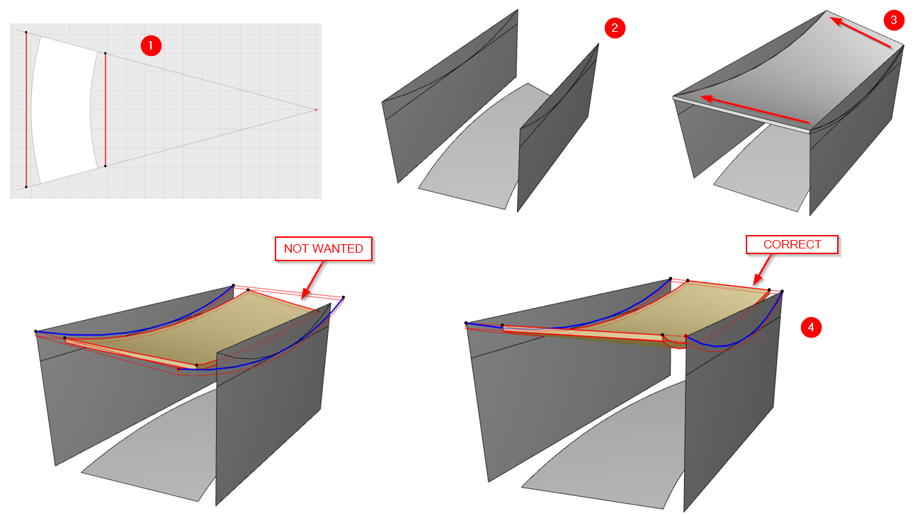
Just changing the shell contour wont't give the desired results. It is the last step though. If you use the shell you have and just change the contour, you won't have horizontal cuts from radial sections because the shell is derived from a planar extrusion, and the contour and sections are cutting it at an angle. See attached, bottom left.
You need to build the extrusion radially, so you can get what you want. You need to trace the projected arcs outside the floor plan contour and build a ruled shell with the two distinct arcs. This should give you the desired results. Note that the shell is segmented, and you won't have perfect horizontal cuts (because of internal triangulation). Nevertheless, that's how I think you should make it.
1. Build a couple of 0 thickness walls before and after the floor plan projection.
2. I used some morph arcs to first build the arc profiles.
3. Using walls and arcs as planes and references, create a ruled shell.
4. Finally edit the shell contour in plan.
Check radial sections.
This is how I understood the problem. Not sure this is the wanted result.
Best regards.
Still looking?
Suggested topics
- Suggestion for wall strategy? interior insulated partition at existing uninsulated exterior wall in Modeling
- Move or rotate multiple Design Options in Modeling
- Multiple buildings with different rotations in Modeling
- Save as DWG in Collaboration with other software
- Cross Selection Not Working Anymore in Documentation
