Turn on suggestions
Auto-suggest helps you quickly narrow down your search results by suggesting possible matches as you type.
Showing results for
Turn on suggestions
Auto-suggest helps you quickly narrow down your search results by suggesting possible matches as you type.
Showing results for
- Graphisoft Community (INT)
- :
- Forum
- :
- Libraries & objects
- :
- Re: Window/doors do not show in Custom Profile Wal...
Options
- Subscribe to RSS Feed
- Mark Topic as New
- Mark Topic as Read
- Pin this post for me
- Bookmark
- Subscribe to Topic
- Mute
- Printer Friendly Page
Libraries & objects
About Archicad and BIMcloud libraries, their management and migration, objects and other library parts, etc.
Window/doors do not show in Custom Profile Wall
Anonymous
Not applicable
Options
- Mark as New
- Bookmark
- Subscribe
- Mute
- Subscribe to RSS Feed
- Permalink
- Report Inappropriate Content
2008-09-15
09:03 PM
- last edited on
2023-05-26
11:30 AM
by
![]() Rubia Torres
Rubia Torres
2008-09-15
09:03 PM
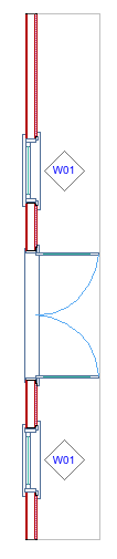
The windows and doors disappear in plan. They convert to a blue dot? I'm not sure what I've done incorrectly.
I'm in Arch 10 on a mac.
Thanks,
Kurt
26 REPLIES 26
Anonymous
Not applicable
Options
- Mark as New
- Bookmark
- Subscribe
- Mute
- Subscribe to RSS Feed
- Permalink
- Report Inappropriate Content
2008-09-24 03:12 AM
Options
- Mark as New
- Bookmark
- Subscribe
- Mute
- Subscribe to RSS Feed
- Permalink
- Report Inappropriate Content
2008-09-24 04:47 AM
2008-09-24
04:47 AM
You seemed to have saved an entire floor - only needed the one problem wall. I'm doing that here: select the problem wall, then
File > External Content > Save Selection as Module ...
The windows and door show up for me - just not inside the wall, partly because of problems with the profile itself...
(continued...)
File > External Content > Save Selection as Module ...
The windows and door show up for me - just not inside the wall, partly because of problems with the profile itself...
(continued...)
AC 28 USA and earlier • macOS Sequoia 15.3, MacBook Pro M2 Max 12CPU/30GPU cores, 32GB
One of the forum moderators
One of the forum moderators
Options
- Mark as New
- Bookmark
- Subscribe
- Mute
- Subscribe to RSS Feed
- Permalink
- Report Inappropriate Content
2008-09-24 04:49 AM
Options
- Mark as New
- Bookmark
- Subscribe
- Mute
- Subscribe to RSS Feed
- Permalink
- Report Inappropriate Content
2008-09-24 04:57 AM
2008-09-24
04:57 AM
In 3D, the windows and door appear way outside the wall cavity... (it is kind of a miracle and a bug at the same time that the windows show up in 2D in one location and in a different location in 3D)...
AC 28 USA and earlier • macOS Sequoia 15.3, MacBook Pro M2 Max 12CPU/30GPU cores, 32GB
One of the forum moderators
One of the forum moderators
Options
- Mark as New
- Bookmark
- Subscribe
- Mute
- Subscribe to RSS Feed
- Permalink
- Report Inappropriate Content
2008-09-24 05:06 AM
2008-09-24
05:06 AM
There's some user error here, and some bugginess.
See the attached screenshot. In Profile Manager, I've turned on only your Construction layer and the Opening Reference. With the Opening Reference layer selected, I issued a 'select all' (cmd-A / ctrl-A).
Note the hotspots in the editor window - and that the Info Box says that there are 2 lines selected.
Bug that I've never seen (so must be fixed now?): The line pen says "1" which is the default black in your pen table, but these lines are invisible and the color swatch in the Info Box looks disabled/pale gray. If I mouse down on the color swatch and choose pen 1 again, these lines show up in black. Weird.
User error - unless these lines were inserted automatically when you saved the profile because you had Opening Reference checked: these lines tell ArchiCAD where the faces of the wall are - so AC thinks this is a really, really thick wall, with the outside face at the edge of the soffit.
Bug - that's still no excuse for the windows/doors appearing far BEYOND the edge of the soffit in 3D. But, hey, this is version 10... [sorry]
(continued...)
See the attached screenshot. In Profile Manager, I've turned on only your Construction layer and the Opening Reference. With the Opening Reference layer selected, I issued a 'select all' (cmd-A / ctrl-A).
Note the hotspots in the editor window - and that the Info Box says that there are 2 lines selected.
Bug that I've never seen (so must be fixed now?): The line pen says "1" which is the default black in your pen table, but these lines are invisible and the color swatch in the Info Box looks disabled/pale gray. If I mouse down on the color swatch and choose pen 1 again, these lines show up in black. Weird.
User error - unless these lines were inserted automatically when you saved the profile because you had Opening Reference checked: these lines tell ArchiCAD where the faces of the wall are - so AC thinks this is a really, really thick wall, with the outside face at the edge of the soffit.
Bug - that's still no excuse for the windows/doors appearing far BEYOND the edge of the soffit in 3D. But, hey, this is version 10...
(continued...)
AC 28 USA and earlier • macOS Sequoia 15.3, MacBook Pro M2 Max 12CPU/30GPU cores, 32GB
One of the forum moderators
One of the forum moderators
Options
- Mark as New
- Bookmark
- Subscribe
- Mute
- Subscribe to RSS Feed
- Permalink
- Report Inappropriate Content
2008-09-24 05:13 AM
2008-09-24
05:13 AM
So, I deleted these reference lines, and drew two new ones at either face of the wall core.
(Note some other problems with the profile - that have nothing to do with windows/doors: the wall could be stretchy vertically, but you've made it fixed height, and you've drawn linework on the drafting layer, hoping I think that your plates would show x's in section. But, that's not the way it works. Drafting layer is ignored - just for helping you put things together. All linework in a profile is generated by the edges of fills. There are lots of other threads where I and others have given tutorials on setting all of this up ... as well as articles on ArchiCADWiki, link above.)
After this change, attached is what I see in 3D...windows and door back in the wall where they belong. Note the materials. You can change the material for every section of a complex profile via the pet palette in the profile editor.
Finally, notice that your wall is hollow. Like real air space. Maybe you want this, because you want a 3D view of studs or something. But, generally, you want to model all skins of a wall with a fill so that you have a solid (except for, e.g., brick wall weep space), and appropriate fills to show up in section.
Karl
AC 28 USA and earlier • macOS Sequoia 15.3, MacBook Pro M2 Max 12CPU/30GPU cores, 32GB
One of the forum moderators
One of the forum moderators
Anonymous
Not applicable
Options
- Mark as New
- Bookmark
- Subscribe
- Mute
- Subscribe to RSS Feed
- Permalink
- Report Inappropriate Content
2008-09-24 06:24 AM
2008-09-24
06:24 AM
Hi Kurt
Karl wrote:"and you've drawn linework on the drafting layer, hoping I think that your plates would show x's in section. But, that's not the way it works"
I don't have all the insight Karl has given you, but thought I'd throw in a bit
of basics on how I got plates to show up in sections.
It works because of the separation of the fills
More can be done, but this is the basics, that work for me.
Bier
Options
- Mark as New
- Bookmark
- Subscribe
- Mute
- Subscribe to RSS Feed
- Permalink
- Report Inappropriate Content
2008-09-24 04:55 PM
2008-09-24
04:55 PM
Thanks, Bier - time constraints led to brevity last night and now...
Your solution is not recommended. The fills should touch, not be separated by a space. The key is the the adjacent fills which should have lines between them should have different fill names.
So, your illustration is perfect for color coding: if you make your green fills 'empty fill' for example and the white wills something else, even a duplicate of empty fill with a new name, then the linework will show up.
In your illustration, you've added quite a few polygons to the model - two for every gap.
With a rectangle that has been broken into four triangles and assigned fills as described, there are no extra polygons. A wall with multiple plates, sheathing etc will still be only 6 polygons - and is much easier/faster to create by using the split command to split rectangular fills - as opposed to doing edge offsets, etc in your method.
Hope that helps.
Cheers,
Karl
AC 28 USA and earlier • macOS Sequoia 15.3, MacBook Pro M2 Max 12CPU/30GPU cores, 32GB
One of the forum moderators
One of the forum moderators
Anonymous
Not applicable
Options
- Mark as New
- Bookmark
- Subscribe
- Mute
- Subscribe to RSS Feed
- Permalink
- Report Inappropriate Content
2008-09-24 05:07 PM
2008-09-24
05:07 PM
Thanks for the tips Karl.
The projects I do are small to medium design/build remodels so not sure a few extra polygons matter, but sure could see how that would add up on large jobs.
And your right it took a while to get the offsets to look right, but figured what the heck, once done was easy to copy or modify for other C.P.s
When I get a chance, I'll see if I can get your method to work for me though.
Thanks!
Bier
Options
- Mark as New
- Bookmark
- Subscribe
- Mute
- Subscribe to RSS Feed
- Permalink
- Report Inappropriate Content
2008-09-24 07:38 PM
2008-09-24
07:38 PM
Bier wrote:You're welcome. Yeah, somebody pointed out in the other thread that the total polygons don't really add up to a significant number. But the gaps can result in light leaking and other strange things in renders of cut models.
Thanks for the tips Karl.
The projects I do are small to medium design/build remodels so not sure a few extra polygons matter, but sure could see how that would add up on large jobs.
Main thing is that the fastest way of generating these things also happens to have the fewest polygons.
Refer to the attached screenshot for steps.
1. Draw rectangular fill the size of the continuous plate or beam.
2. Select the fill, and issue the 'split' command (cmd-B / ctrl-B), and click from one corner to the diagonally opposite one. You'll get an eyeball to indicate which side of the split you want selected. Click anywhere, since it doesn't matter here - we want to select both halves for the next step...
3. Shift-click to select the other half of the split rectangle if not already selected. Again, split command (cmd-B / ctrl-B), and click on the other diagonal points.
4. Finally, select opposite triangles and assign them a different fill via the Info Box.
The cmd-b (ctrl-b) keystroke may not be in everyone's work environment - it is the really old shortcut for the split command, which I still use from habit. Your shortcut may be different.
I agree - once it is done, you just copy/paste into other profiles. But, like anything else, if we copy/paste something 'clean', then we have clean stuff everywhere.
Related to this - supposed someone wants to show rebar in a footing? If you cut circular holes in a footing fill, you'll see circles in section - but they will not have a fill (they are genuinely tubules of 'air' once extruded). Magic wanding the resulting holes with a fill (solid black maybe?) will result in black circles appearing in section...and many fewer polygons.
Cheers,
Karl

AC 28 USA and earlier • macOS Sequoia 15.3, MacBook Pro M2 Max 12CPU/30GPU cores, 32GB
One of the forum moderators
One of the forum moderators
Related articles
Didn't find the answer?
Check other topics in this Forum
Back to ForumRead the latest accepted solutions!
Accepted SolutionsStart a new conversation!
