Turn on suggestions
Auto-suggest helps you quickly narrow down your search results by suggesting possible matches as you type.
Showing results for
Turn on suggestions
Auto-suggest helps you quickly narrow down your search results by suggesting possible matches as you type.
Showing results for
- Graphisoft Community (INT)
- :
- Knowledge Base
- :
- Modeling
- :
- How to Work Precisely in Archicad
Options
- Subscribe to RSS Feed
- Mark as New
- Mark as Read
- Bookmark
- Subscribe to Topic
- Printer Friendly Page
- Report Inappropriate Content
How to Work Precisely in Archicad
Graphisoft
Options
- Subscribe to RSS Feed
- Mark as New
- Mark as Read
- Bookmark
- Subscribe to Topic
- Printer Friendly Page
- Report Inappropriate Content
on
2019-02-06
01:51 PM
- edited on
2022-11-11
01:35 PM
by
Giovana Benvenuto
In Archicad the flexibility is given for just sketching up the building without having to numerically specify the correct size or location of an element, but if it's coming to a proper design process, you have to place the elements with a certain size and position. With the help of the following input aids you can define the size (e.g. has to have the same length as another element) and position (e.g. the wall has to be parallel with a another wall) in relation to already existing elements or also independently from other elements. Click + to expand the list and see the details.
Guide Lines
Guide Lines are permanent lines and arcs that can be placed manually. They are permanent, so they remain until you remove them. Guide Lines can be placed in 2D and in 3D as well, however there is no connection between them, they are unique in each view. For more information see Guide Lines
Snap References
Snap References are temporary lines, arcs and points that appear along existing elements, to assist accurate element placement. There are two types of Snap References: To make them appear at multiple places that are relevant to your input, you can define any edges or points as Snap References. Activate a Snap Reference (a dynamically appearing blue highlight) by hovering the cursor over element edges or points. (You can deactivate them by hovering over the Snap Reference.) You can activate any number of Snap References simultaneously. Once you have defined Snap References, you will see Snap Guides and Points appear. They appear with a blue dashed lines and arcs/circles.Snap Guides indicate the relation:
- Tangent
- Parallel
- Perpendicular
- Angle Bisector (if applicable)
- The line connecting two circles’ centerpoints (if applicable)


Trace and Reference
In Archicad, you can lay a view under another view in any model or layout window. It makes it easy to compare model views/drawings on the same screen or you can use it as a temporary editing aid. For more information see- Virtual Trace: Using References to Edit and Compare Model Views and Drawings
- Trace & Reference Palette

Magic Wand
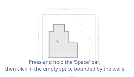
The Magic Wand (shortcut: Spacebar) finds and traces a linear or polygonal shape from among existing elements, and then helps generate a new element based on the traced polygon. Magic Wand can be used in 2D and in 3D as well.
- If you click on an edge or node, the Magic Wand traces the element and/or the element chain.
- If you click in empty space, or on a surface, the Magic Wand traces the closed polygonal area formed by the nearest elements.

Intelligent Cursor
In Archicad the cursor shape indicates the actual position of the cursor helping you to find edges, points or reference lines. For more informations see Intelligent Cursor
Tracker
For entering distances in Archicad the Tracker is used. Entering distances works the same way in 2D and in 3D. The Tracker appears during element input and it follows your mouse movements, constantly providing feedback about the distance and angle or/and the XYZ coordinates calculated from the starting node. Use the dialog box at Options > Project Preferences > Working Units to define the units are displayed in the Tracker. For more information see How to enter distances in Archicad
Construction Grid and Snap Grid
Construction Grid and Snap Grid are provided to help you make drafting easier. The difference between them is, that the Snap Grid is an invisible grid that you can use optionally to make input easier, by having the cursor snap to a predefined distance. The Construction Grid is visible, it can be rotated and if the “Snap to Construction Grid” option is checked, the grid crossing points can be snapped to as well. Grids can be defined separately for the Floor Plan and any individual Section/Elevation/IE, 3D Document, Detail/Worksheet, or Layout window. (Note: in Floor Plan window, the same Grid settings will be used for all Stories.) For more information see
Measure Tool
The Measure Tool allows you to measure distances and areas in 2D and in 3D as well. It is a temporary, on-screen function and can be used for a quick check up. (If you want to display the size of an element permanently, use the Dimension Tool or the Label Tool.) Use the dialog box at Options > Project Preferences > Working Units to define the units displayed by the Measure Tool.
Labels:
Related articles
- How to format schedules in Archicad? in Documentation
- Import architectural models or 2D drawings into Graphisoft's MEP Designer in MEP
- Creating layouts in Archicad: Master Layouts, Autotexts, graphics, and more in Documentation
- Graphisoft MEP Designer: Quick-start guide for new users in Getting started
- macOS 26 Tahoe in Installation & update
