
Turn on suggestions
Auto-suggest helps you quickly narrow down your search results by suggesting possible matches as you type.
Showing results for
EN
Turn on suggestions
Auto-suggest helps you quickly narrow down your search results by suggesting possible matches as you type.
Showing results for
- English
- :
- Forum
- :
- Libraries & objects
- :
- Re: 2D Symbol Insertion Point using GDL scripting
Options
- Subscribe to RSS Feed
- Mark Topic as New
- Mark Topic as Read
- Pin this post for me
- Bookmark
- Subscribe to Topic
- Mute
- Printer Friendly Page
Anonymous
Not applicable
Options
- Mark as New
- Bookmark
- Subscribe
- Mute
- Subscribe to RSS Feed
- Permalink
- Report Inappropriate Content
2019-09-10
03:39 AM
- last edited on
2023-05-24
09:54 AM
by
![]() Rubia Torres
Rubia Torres
2D Symbol Insertion Point using GDL scripting
2019-09-10
03:39 AM
I'm fairly new to GDL and scripting in Archicad all together but I'm in urgent need of creating this specific type of door for my project. This door began as a Revit door which I was able to import using the Import RFA as GDL plugin. I was able to tidy up the door and I'm fairly happy with it but I also wanted to add an extra feature in the door's settings to be able to switch between the door's level of detail of its 2D symbol in plan view.
Revit has the ability to show coarse, medium and fine views of its elements. If you look at what I'm trying to do, I've added some scripting where I can choose between 3 levels of details. I then exported the door's 2d symbol from Revit for all 3 settings, saved each as an object in Archicad and was able to copy the 2D code that defines each symbol.
My issue is now how do I make each symbol insert and snap to the overall door's width and thickness? If you look at my screenshots, the symbols just float because the code is currently picking a random x and y insertion points. Can anyone help me, please?
Thanks
19 Replies 19
Barry Kelly
Moderator
Options
- Mark as New
- Bookmark
- Subscribe
- Mute
- Subscribe to RSS Feed
- Permalink
- Report Inappropriate Content
2019-09-10 07:48 AM
2019-09-10
07:48 AM
I am not sure how this is going to work for you as there is quite a bit to door and window objects.
But the line ...
That code should be followed by a ...
You can measure in the 2D preview window so you can see what values to use for the x and y co-ordinates in the ADD2 command.
Barry.
But the line ...
ADD2 -0, -0Is the one that will move the lines created by the following code.
That code should be followed by a ...
DEL 1to undo the move ready for the next bit of code.
You can measure in the 2D preview window so you can see what values to use for the x and y co-ordinates in the ADD2 command.
Barry.
One of the forum moderators.
Versions 6.5 to 27
i7-10700 @ 2.9Ghz, 32GB ram, GeForce RTX 2060 (6GB), Windows 10
Lenovo Thinkpad - i7-1270P 2.20 GHz, 32GB RAM, Nvidia T550, Windows 11
Versions 6.5 to 27
i7-10700 @ 2.9Ghz, 32GB ram, GeForce RTX 2060 (6GB), Windows 10
Lenovo Thinkpad - i7-1270P 2.20 GHz, 32GB RAM, Nvidia T550, Windows 11
Anonymous
Not applicable
Options
- Mark as New
- Bookmark
- Subscribe
- Mute
- Subscribe to RSS Feed
- Permalink
- Report Inappropriate Content
2019-09-10 10:07 AM
2019-09-10
10:07 AM
Thanks for the reply. Is there any code I can add to manipulate the level of detail using the "model view options" instead?
Barry Kelly
Moderator
Options
- Mark as New
- Bookmark
- Subscribe
- Mute
- Subscribe to RSS Feed
- Permalink
- Report Inappropriate Content
2019-09-10 10:49 AM
2019-09-10
10:49 AM
Studioverde wrote:Sure - but you say you are new to this GDL scripting.
Is there any code I can add to manipulate the level of detail using the "model view options" instead?
You could open a Graphisoft window and try to dig through the scripts to see how it is done, but that is not so easy.
Basically what you are looking for is the 'LIBRARYGLOBAL' command - you will find it in the GDL manual.
This will allow you to find out the values of the MVO paramerters and then based on those values you can run the parts of your script that you want.
To give you more specifics, I would have to go digging around in the GS library myself (I don't actually use their library as I have my own) so that is about the limit of my help for now.
Maybe someone else has done this already and can point you where to go.
The other thing you can try is to contact your local distributor.
There is an add-on called Library Part Maker that is available to some regions (UK for example).
This will allow you to create objects, doors and windows (non-parametric) that are based on the LOD settings in the MVO.
I have searched the forum here for Library part maker, and all of the posts seem to say ...
the availability of the LPM add-on might wary depending on your country. Contacting your local support might be the best choice hereSo contact your local distributor and see what they say.
Barry.
One of the forum moderators.
Versions 6.5 to 27
i7-10700 @ 2.9Ghz, 32GB ram, GeForce RTX 2060 (6GB), Windows 10
Lenovo Thinkpad - i7-1270P 2.20 GHz, 32GB RAM, Nvidia T550, Windows 11
Versions 6.5 to 27
i7-10700 @ 2.9Ghz, 32GB ram, GeForce RTX 2060 (6GB), Windows 10
Lenovo Thinkpad - i7-1270P 2.20 GHz, 32GB RAM, Nvidia T550, Windows 11
Barry Kelly
Moderator
Options
- Mark as New
- Bookmark
- Subscribe
- Mute
- Subscribe to RSS Feed
- Permalink
- Report Inappropriate Content
2019-09-10 11:15 AM
2019-09-10
11:15 AM
I had a couple of minutes to go looking.
This is the macro that controls the MVO for doors and windows.
The parameters you will be looking for the values of are ...
Hope this helps.
Barry.
This is the macro that controls the MVO for doors and windows.
The parameters you will be looking for the values of are ...
Hope this helps.
Barry.
One of the forum moderators.
Versions 6.5 to 27
i7-10700 @ 2.9Ghz, 32GB ram, GeForce RTX 2060 (6GB), Windows 10
Lenovo Thinkpad - i7-1270P 2.20 GHz, 32GB RAM, Nvidia T550, Windows 11
Versions 6.5 to 27
i7-10700 @ 2.9Ghz, 32GB ram, GeForce RTX 2060 (6GB), Windows 10
Lenovo Thinkpad - i7-1270P 2.20 GHz, 32GB RAM, Nvidia T550, Windows 11
Anonymous
Not applicable
Options
- Mark as New
- Bookmark
- Subscribe
- Mute
- Subscribe to RSS Feed
- Permalink
- Report Inappropriate Content
2019-09-24 12:51 AM
2019-09-24
12:51 AM
Hi Barry,
Thanks for looking this up for me. I think due to my lack of knowledge of GDL, I have not set up the creation of these windows correctly nor have I used the right procedure. I need to hand over this content to my client by the end of this coming week but I will invest time into learning GDL and the proper procedures into creating content.
For the time being I wanted to ask you about two further features that I would like to implement and wondering if I could get your help.
Feature 1 - Implement a code where when A (width) is greater than 5000mm, the width of the window does not change meaning you can only adjust the width of the window between 1mm to 5000mm and nothing greater than that.
I'm obviously a begginer at best when it comes to GDL coding but my assumption to get this to work would be,
IF A => 5000 (IF STATEMENT)
THEN LOCK A
That is my logic as to how this will work but what is the exact code? I dont know.
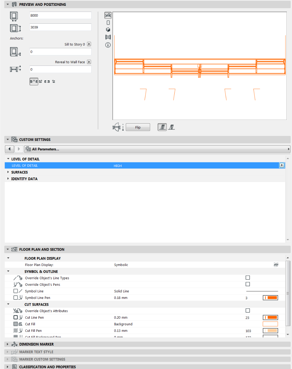
Feature 2 - I managed to get the 3 different level of details to work by saving each 2D view as a library object and extracting the code for each and plugging it in to the 2d script of the window. (please see attached screenshot). However, when I change the real width of the window say from 5000mm to 3000mm, the opening of it does change but the 2D symbol remain static and does not change. Is there any way I can link the 2D script symbol to the 3D object?
These are the 2 features that I still need to implement for now. Any help would be great.
Thank you
Thanks for looking this up for me. I think due to my lack of knowledge of GDL, I have not set up the creation of these windows correctly nor have I used the right procedure. I need to hand over this content to my client by the end of this coming week but I will invest time into learning GDL and the proper procedures into creating content.
For the time being I wanted to ask you about two further features that I would like to implement and wondering if I could get your help.
Feature 1 - Implement a code where when A (width) is greater than 5000mm, the width of the window does not change meaning you can only adjust the width of the window between 1mm to 5000mm and nothing greater than that.
I'm obviously a begginer at best when it comes to GDL coding but my assumption to get this to work would be,
IF A => 5000 (IF STATEMENT)
THEN LOCK A
That is my logic as to how this will work but what is the exact code? I dont know.
Feature 2 - I managed to get the 3 different level of details to work by saving each 2D view as a library object and extracting the code for each and plugging it in to the 2d script of the window. (please see attached screenshot). However, when I change the real width of the window say from 5000mm to 3000mm, the opening of it does change but the 2D symbol remain static and does not change. Is there any way I can link the 2D script symbol to the 3D object?
These are the 2 features that I still need to implement for now. Any help would be great.
Thank you
Barry Kelly
Moderator
Options
- Mark as New
- Bookmark
- Subscribe
- Mute
- Subscribe to RSS Feed
- Permalink
- Report Inappropriate Content
2019-09-24 03:25 AM
2019-09-24
03:25 AM
Feature 1.
Put this code in the Parameter script.
This will restrict the input width of the window to that range only.
Feature 2.
Unfortunately your 2D script is placing lines of fixed dimensions.
If you want to make the 2D parametric then the code for the line for the width of the window would have to be would have to be ...
However you could add a MUL2 command to stretch the following code.
The problem is it will all be relative, so yes your window will change width, but the frame width will also change proportionally as well.
Say the original window you drew was 2400mm wide.
It will always be 2400mm wide in 2D.
After the 'ADD A,B' line you will need to put the line ...
Then 'DEL 1' to undo the MUL2 (and another 'DEL 1' to undo the original ADD as well - always move back to your origin so you know where you are).
So now if the window is 2400mm wide it will be MULtiplied by 1 (2.200/2.400)
If you make the window 4800mm wide it will be MULtiplied by 2 (4.800/2.400)
But as I say the frame widths will also be doubled.
The only way you can avoid that is to script each and every line with a relationship to the 'A' width.
i.e. LINE2 A-frame_width,0, A-frame_width, frame_depth ... will draw a line the depth of your window frame but always the frame width inside of the length A.
Barry.
Put this code in the Parameter script.
VALUES "A" RANGE [0.001, 5.000]
This will restrict the input width of the window to that range only.
Feature 2.
Unfortunately your 2D script is placing lines of fixed dimensions.
If you want to make the 2D parametric then the code for the line for the width of the window would have to be would have to be ...
LINE2 0,0,A,0To change all of the lines of code so they are relative to the width (A) would be rather tedious.
However you could add a MUL2 command to stretch the following code.
The problem is it will all be relative, so yes your window will change width, but the frame width will also change proportionally as well.
Say the original window you drew was 2400mm wide.
It will always be 2400mm wide in 2D.
After the 'ADD A,B' line you will need to put the line ...
MUL2 A/2.400, 1Then you have the code to draw the window frame
Then 'DEL 1' to undo the MUL2 (and another 'DEL 1' to undo the original ADD as well - always move back to your origin so you know where you are).
So now if the window is 2400mm wide it will be MULtiplied by 1 (2.200/2.400)
If you make the window 4800mm wide it will be MULtiplied by 2 (4.800/2.400)
But as I say the frame widths will also be doubled.
The only way you can avoid that is to script each and every line with a relationship to the 'A' width.
i.e. LINE2 A-frame_width,0, A-frame_width, frame_depth ... will draw a line the depth of your window frame but always the frame width inside of the length A.
Barry.
One of the forum moderators.
Versions 6.5 to 27
i7-10700 @ 2.9Ghz, 32GB ram, GeForce RTX 2060 (6GB), Windows 10
Lenovo Thinkpad - i7-1270P 2.20 GHz, 32GB RAM, Nvidia T550, Windows 11
Versions 6.5 to 27
i7-10700 @ 2.9Ghz, 32GB ram, GeForce RTX 2060 (6GB), Windows 10
Lenovo Thinkpad - i7-1270P 2.20 GHz, 32GB RAM, Nvidia T550, Windows 11
Lingwisyer
Guru
Options
- Mark as New
- Bookmark
- Subscribe
- Mute
- Subscribe to RSS Feed
- Permalink
- Report Inappropriate Content
2019-09-24 03:28 AM
2019-09-24
03:28 AM
Studioverde wrote:The 2D and 3D are seperate things. You will need to copy the code from the 3D script as well.
extracting the code for each and plugging it in to the 2d script of the window.
Studioverde wrote:You should read up the Parameters section of the GDL Reference Guide. This statement of yours will just prevent you from doing anything after changing the value of A. What you are wanting is:
IF A => 5000 (IF STATEMENT)
THEN LOCK A
IF A => 5000 then PARAMETERS A = 5000Edit: though doing as Barry has suggested using
If you are really wanting to create parametric windows, you will have to script them from scratch as it will be next to impossible to scale parts individually if saved out from modelled parts as per what Barry has said regarding
2D Script
mul2 A / 8.00000, B / 0.457522to
mul2 A / 8.00000, 1
3D Script
mulx	A / 8.00000
muly	B / 0.457522
to
mulx	A / 8.00000
muly	1
Ling.
| AC22-29 AUS 3200 | Help Those Help You - Add a Signature |
| Self-taught, bend it till it breaks | Creating a Thread |
| Win11 | i9 10850K | 64GB | RX6600 | Win11 | 7800X3D | 32GB | RTX5070TI |
Anonymous
Not applicable
Options
- Mark as New
- Bookmark
- Subscribe
- Mute
- Subscribe to RSS Feed
- Permalink
- Report Inappropriate Content
2019-09-24 06:36 AM
2019-09-24
06:36 AM
Thank you for your help. Barry feature 1 worked like a charm so thank you. However for feature 2, something is still not working in the code after I added in the code you've suggested but maybe I have not added in the code correctly. Please see attached the start of the code and the end of the code and the error messageS that I get when I check the code. One of the error messages is before I place the DEL1 code at the bottom of the window frame code but after I added in both DEL1 lines, I get the code that talks about the missing CALL keyword.
Lingwisyer
Guru
Options
- Mark as New
- Bookmark
- Subscribe
- Mute
- Subscribe to RSS Feed
- Permalink
- Report Inappropriate Content
2019-09-24 06:56 AM
2019-09-24
06:56 AM
You want your second value in the MUL command to be 1, not 0.
You need a space between the DEL and the number. It maybe viable to use "DEL TOP" in this situation.
Ling.
You need a space between the DEL and the number. It maybe viable to use "DEL TOP" in this situation.
Ling.
| AC22-29 AUS 3200 | Help Those Help You - Add a Signature |
| Self-taught, bend it till it breaks | Creating a Thread |
| Win11 | i9 10850K | 64GB | RX6600 | Win11 | 7800X3D | 32GB | RTX5070TI |
Didn't find the answer?
Check other topics in this Forum
Back to ForumRead the latest accepted solutions!
Accepted SolutionsStart a new conversation!
Suggested topics
- Parametric 2D window symbol in Libraries & objects
- Archicad vs Revit ability to create custom objects in Modeling
- Stretchy 2D symbol made from fragments? in Libraries & objects
- GLOB_CUTPLANES_INFO[1] inconsistency in Libraries & objects
- 2D Symbol Insertion Point using GDL scripting in Libraries & objects
