Turn on suggestions
Auto-suggest helps you quickly narrow down your search results by suggesting possible matches as you type.
Showing results for
Turn on suggestions
Auto-suggest helps you quickly narrow down your search results by suggesting possible matches as you type.
Showing results for
- Graphisoft Community (INT)
- :
- Forum
- :
- Modeling
- :
- Complex Profile Help
Options
- Subscribe to RSS Feed
- Mark Topic as New
- Mark Topic as Read
- Pin this post for me
- Bookmark
- Subscribe to Topic
- Mute
- Printer Friendly Page
Modeling
About Archicad's design tools, element connections, modeling concepts, etc.
SOLVED!
Complex Profile Help
Anonymous
Not applicable
Options
- Mark as New
- Bookmark
- Subscribe
- Mute
- Subscribe to RSS Feed
- Permalink
- Report Inappropriate Content
2019-12-16
07:57 AM
- last edited on
2023-05-09
04:18 PM
by
![]() Rubia Torres
Rubia Torres
2019-12-16
07:57 AM
Profile shown to give you an idea:

Now when I place doors/windows on this wall they are showing correct on the floor plans however they look wrong in 3d and elevations/sections. Adding a reveal seems to help but then that messes up the floor plan view pushing the windows further inside.
Id really love for the floor plans to stay as they are now but the elevations/3d to not have this issue going through it all, yet id like to have the wall automatically cut the openings for the windows/doors too.
Is there a way to show all the information correct without having to do separate walls and cutting holes in them for the low block wall around the outside?
Hope this makes sense.
Reference images:


Solved! Go to Solution.
1 ACCEPTED SOLUTION
Accepted Solutions
Solution
Options
- Mark as New
- Bookmark
- Subscribe
- Mute
- Subscribe to RSS Feed
- Permalink
- Report Inappropriate Content
2019-12-17 03:03 AM
2019-12-17
03:03 AM
Just playing with this a little more.
You can stagger the opening reference line to follow the contour of your wall.
This way the window position in 3D will follow this opening reference position.
It does depend on whether you have the window anchor set to head or sill too, as that is what will anchor to the opening reference line.
Still the 2D view of the window will only be accurate if you have it set to 'Projected' or 'Projected with Overhead'.
I still wish the 'Symbolic' floor plan view could offset from the reference line as well - that would be perfect.
Barry.
One of the forum moderators.
Versions 6.5 to 27
i7-10700 @ 2.9Ghz, 32GB ram, GeForce RTX 2060 (6GB), Windows 10
Lenovo Thinkpad - i7-1270P 2.20 GHz, 32GB RAM, Nvidia T550, Windows 11
Versions 6.5 to 27
i7-10700 @ 2.9Ghz, 32GB ram, GeForce RTX 2060 (6GB), Windows 10
Lenovo Thinkpad - i7-1270P 2.20 GHz, 32GB RAM, Nvidia T550, Windows 11
8 REPLIES 8
Options
- Mark as New
- Bookmark
- Subscribe
- Mute
- Subscribe to RSS Feed
- Permalink
- Report Inappropriate Content
2019-12-16 09:29 AM
2019-12-16
09:29 AM
Funny, I was literally just revisiting this problem myself.
I originally posted about it here.
https://archicad-talk.graphisoft.com/viewtopic.php?f=20&t=62812
The problem is in 3D (section & elevation), the window reveal is offset from the opening line reference in the complex profile.
The 'Symbolic' floor plan display view of the window does not match this 3D position.
You need to switch the floor plan display of the window to 'Projected with overhead' so it matches the 3D.
Problem is this looks awful in plan - I want to see the window with the symbolic 2D view.
I am playing around at the moment adding an offset parameter in 2D, so I can match the 2D symbolic position with the 3D position.
It seems to be working so far, but I have my own custom windows so there is no problem in me editing the scripts.
You could try adjusting the position of the opening reference line in the complex profile.
Barry.
I originally posted about it here.
The problem is in 3D (section & elevation), the window reveal is offset from the opening line reference in the complex profile.
The 'Symbolic' floor plan display view of the window does not match this 3D position.
You need to switch the floor plan display of the window to 'Projected with overhead' so it matches the 3D.
Problem is this looks awful in plan - I want to see the window with the symbolic 2D view.
I am playing around at the moment adding an offset parameter in 2D, so I can match the 2D symbolic position with the 3D position.
It seems to be working so far, but I have my own custom windows so there is no problem in me editing the scripts.
You could try adjusting the position of the opening reference line in the complex profile.
Barry.
One of the forum moderators.
Versions 6.5 to 27
i7-10700 @ 2.9Ghz, 32GB ram, GeForce RTX 2060 (6GB), Windows 10
Lenovo Thinkpad - i7-1270P 2.20 GHz, 32GB RAM, Nvidia T550, Windows 11
Versions 6.5 to 27
i7-10700 @ 2.9Ghz, 32GB ram, GeForce RTX 2060 (6GB), Windows 10
Lenovo Thinkpad - i7-1270P 2.20 GHz, 32GB RAM, Nvidia T550, Windows 11
Anonymous
Not applicable
Options
- Mark as New
- Bookmark
- Subscribe
- Mute
- Subscribe to RSS Feed
- Permalink
- Report Inappropriate Content
2019-12-16 11:28 AM
2019-12-16
11:28 AM
Barry wrote:Thanks for that Barry.
Funny, I was literally just revisiting this problem myself.
I originally posted about it here.
https://archicad-talk.graphisoft.com/viewtopic.php?f=20&t=62812
The problem is in 3D (section & elevation), the window reveal is offset from the opening line reference in the complex profile.
The 'Symbolic' floor plan display view of the window does not match this 3D position.
You need to switch the floor plan display of the window to 'Projected with overhead' so it matches the 3D.
Problem is this looks awful in plan - I want to see the window with the symbolic 2D view.
I am playing around at the moment adding an offset parameter in 2D, so I can match the 2D symbolic position with the 3D position.
It seems to be working so far, but I have my own custom windows so there is no problem in me editing the scripts.
You could try adjusting the position of the opening reference line in the complex profile.
Barry.
Ive always ended up doing it with an extra wall and cutting openings for it but was hoping maybe there was a better solution.
What do you mean by adjusting the position of the opening reference line in the complex profile, could you help me in what I need to do for that? I have little experience with the modifiers in complex profiles.
Anonymous
Not applicable
Options
- Mark as New
- Bookmark
- Subscribe
- Mute
- Subscribe to RSS Feed
- Permalink
- Report Inappropriate Content
2019-12-16 01:07 PM
Anonymous
Not applicable
Options
- Mark as New
- Bookmark
- Subscribe
- Mute
- Subscribe to RSS Feed
- Permalink
- Report Inappropriate Content
2019-12-17 01:28 AM
2019-12-17
01:28 AM
Braza wrote:Thanks Barry.
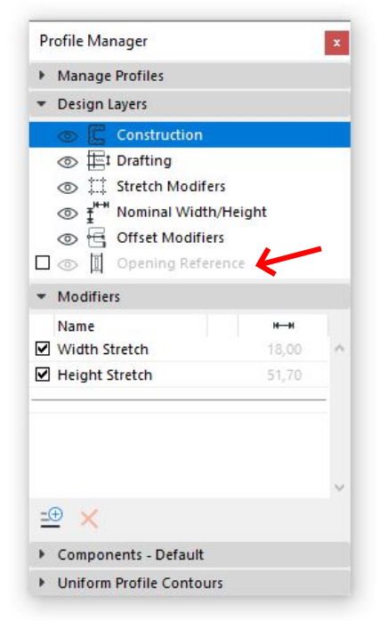
Its in the Profile Manager.
You make it active with the checkbox, then adjust the lines within the profile on the right position.
One last question, how would you go about having a glass corner window on one of these walls, the tool doesnt seem to work on custom profiles.
Options
- Mark as New
- Bookmark
- Subscribe
- Mute
- Subscribe to RSS Feed
- Permalink
- Report Inappropriate Content
2019-12-17 02:09 AM
2019-12-17
02:09 AM
nonco wrote:
Braza wrote:Thanks Barry.
Its in the Profile Manager.
You make it active with the checkbox, then adjust the lines within the profile on the right position.
One last question, how would you go about having a glass corner window on one of these walls, the tool doesnt seem to work on custom profiles.
That was actually Braza.
Sometimes however I am called Bazza.
I don't actually use the default GS windows as I have my own custom objects.
I know the GS winows have corner options, do these not work at all in the complex profile wall?
I am not talking about the corner window tool, just the corner options in the windows themselves.
Add two windows, set the corner options and then move them together to make the join.
Barry.
One of the forum moderators.
Versions 6.5 to 27
i7-10700 @ 2.9Ghz, 32GB ram, GeForce RTX 2060 (6GB), Windows 10
Lenovo Thinkpad - i7-1270P 2.20 GHz, 32GB RAM, Nvidia T550, Windows 11
Versions 6.5 to 27
i7-10700 @ 2.9Ghz, 32GB ram, GeForce RTX 2060 (6GB), Windows 10
Lenovo Thinkpad - i7-1270P 2.20 GHz, 32GB RAM, Nvidia T550, Windows 11
Solution
Options
- Mark as New
- Bookmark
- Subscribe
- Mute
- Subscribe to RSS Feed
- Permalink
- Report Inappropriate Content
2019-12-17 03:03 AM
2019-12-17
03:03 AM
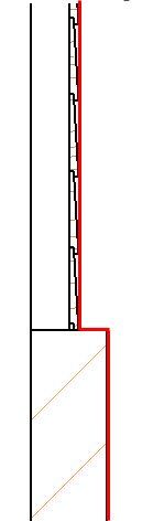
Just playing with this a little more.
You can stagger the opening reference line to follow the contour of your wall.
This way the window position in 3D will follow this opening reference position.
It does depend on whether you have the window anchor set to head or sill too, as that is what will anchor to the opening reference line.
Still the 2D view of the window will only be accurate if you have it set to 'Projected' or 'Projected with Overhead'.
I still wish the 'Symbolic' floor plan view could offset from the reference line as well - that would be perfect.
Barry.
You can stagger the opening reference line to follow the contour of your wall.
This way the window position in 3D will follow this opening reference position.
It does depend on whether you have the window anchor set to head or sill too, as that is what will anchor to the opening reference line.
Still the 2D view of the window will only be accurate if you have it set to 'Projected' or 'Projected with Overhead'.
I still wish the 'Symbolic' floor plan view could offset from the reference line as well - that would be perfect.
Barry.
One of the forum moderators.
Versions 6.5 to 27
i7-10700 @ 2.9Ghz, 32GB ram, GeForce RTX 2060 (6GB), Windows 10
Lenovo Thinkpad - i7-1270P 2.20 GHz, 32GB RAM, Nvidia T550, Windows 11
Versions 6.5 to 27
i7-10700 @ 2.9Ghz, 32GB ram, GeForce RTX 2060 (6GB), Windows 10
Lenovo Thinkpad - i7-1270P 2.20 GHz, 32GB RAM, Nvidia T550, Windows 11
Anonymous
Not applicable
Options
- Mark as New
- Bookmark
- Subscribe
- Mute
- Subscribe to RSS Feed
- Permalink
- Report Inappropriate Content
2019-12-17 03:31 AM
2019-12-17
03:31 AM
Barry wrote:Whoops, was still a bit tired when reading it, my mistake.
nonco wrote:
Braza wrote:Thanks Barry.
Its in the Profile Manager.
You make it active with the checkbox, then adjust the lines within the profile on the right position.
One last question, how would you go about having a glass corner window on one of these walls, the tool doesnt seem to work on custom profiles.
That was actually Braza.
Sometimes however I am called Bazza.
I don't actually use the default GS windows as I have my own custom objects.
I know the GS winows have corner options, do these not work at all in the complex profile wall?
I am not talking about the corner window tool, just the corner options in the windows themselves.
Add two windows, set the corner options and then move them together to make the join.
Barry.
It was giving me some errors before but trying your way with just changing the corner options is working for me now thanks. For some reason it wasnt showing Glass as an option when I was trying earlier but is okay now.
Anonymous
Not applicable
Options
- Mark as New
- Bookmark
- Subscribe
- Mute
- Subscribe to RSS Feed
- Permalink
- Report Inappropriate Content
2019-12-17 03:32 AM
2019-12-17
03:32 AM
Barry wrote:Yeah I tried staggering it and was causing some issues that I might be able to fix but just changing the line even being straight seems to give me the desired outcome I was looking for if I turn off outside casing. Might not be completely perfect not showing casing but for what I need it does the job great thanks
Just playing with this a little more.
You can stagger the opening reference line to follow the contour of your wall.
opening_reference_4.jpg
This way the window position in 3D will follow this opening reference position.
It does depend on whether you have the window anchor set to head or sill too, as that is what will anchor to the opening reference line.
Still the 2D view of the window will only be accurate if you have it set to 'Projected' or 'Projected with Overhead'.
I still wish the 'Symbolic' floor plan view could offset from the reference line as well - that would be perfect.
Barry.
Suggested content
- Complex Profile custom edge surface selection in Project data & BIM
- Missing outlines in openings in complex profile walls. in Modeling
- Rail Glass Panels Not Connecting at the Corner + Bottom Rail Misalignment in Modeling
- Introduction: ViBIM – Specialized Partner for Scan to BIM & Revit Modeling in General discussions
- Character padding limit in expressions in Project data & BIM
Still looking?
