
Turn on suggestions
Auto-suggest helps you quickly narrow down your search results by suggesting possible matches as you type.
Showing results for
EN
Turn on suggestions
Auto-suggest helps you quickly narrow down your search results by suggesting possible matches as you type.
Showing results for
- English
- :
- Forum
- :
- Libraries & objects
- :
- Re: Project2{4} Usage
Options
- Subscribe to RSS Feed
- Mark Topic as New
- Mark Topic as Read
- Pin this post for me
- Bookmark
- Subscribe to Topic
- Mute
- Printer Friendly Page
Lingwisyer
Guru
Options
- Mark as New
- Bookmark
- Subscribe
- Mute
- Subscribe to RSS Feed
- Permalink
- Report Inappropriate Content
2018-10-04
11:41 AM
- last edited on
2022-09-23
02:26 PM
by
![]() Oleksandra Vakariuk
Oleksandra Vakariuk
Project2{4} Usage
2018-10-04
11:41 AM
Hi all,
When using Project2{4}, is the second set of definitions the infinite cut plane settings as in the guide it says "...(numCutplanes+1)"? Anyway, I am trying to get a projection at a defined height through my object, but I seem to only get the uncut projection...
Also, how do I go about defining the wall closure? Even just simple closing lines matching the wall cut lines.
Ling.
When using Project2{4}, is the second set of definitions the infinite cut plane settings as in the guide it says "...(numCutplanes+1)"? Anyway, I am trying to get a projection at a defined height through my object, but I seem to only get the uncut projection...
PROJECT2{4} 5, 90,					!projection_code, angle,
	0, 1+2,								!useTransparency, statusParts,
	1,									!numCutplanes,
	b/2 + gs_fw_lower - gs_fw_upper,		!cutplaneHeight1, ..., cutplaneHeightn,

	2, 1+2+4+8+64,						!method1, parts1,
	gs_fill_type,							!cutFillIndex1,
	gs_fill_pen, gs_back_pen,				!cutFillFgPen1, cutFillBgPen1,
	0, 0, 0,								!cutFillOrigoX1, cutFillOrigoY1, cutFillDirection1,
	gs_cut_pen,	1,						!cutLinePen1, cutLineType1,
	65,									!projectedFillIndex1,
	19, 19,								!projectedFillFgPen1, projectedFillBgPen1,
	0, 0, 0,								!projectedFillOrigoX1, projectedFillOrigoY1, projectedFillDirection1,
	gs_pen_2D, 1,						!projectedLinePen1, projectedLineType1

	2, 1+2+4+8+64,						!method1, parts1,
	gs_fill_type,							!cutFillIndex1,
	gs_fill_pen, gs_back_pen,				!cutFillFgPen1, cutFillBgPen1,
	0, 0, 0,								!cutFillOrigoX1, cutFillOrigoY1, cutFillDirection1,
	gs_cut_pen,	4,						!cutLinePen1, cutLineType1,
	65,									!projectedFillIndex1,
	19, 19,								!projectedFillFgPen1, projectedFillBgPen1,
	0, 0, 0,								!projectedFillOrigoX1, projectedFillOrigoY1, projectedFillDirection1,
	gs_pen_2D, 4						!projectedLinePen1, projectedLineType1
Also, how do I go about defining the wall closure? Even just simple closing lines matching the wall cut lines.
Ling.
| AC22-29 AUS 3200 | Help Those Help You - Add a Signature |
| Self-taught, bend it till it breaks | Creating a Thread |
| Win11 | i9 10850K | 64GB | RX6600 | Win11 | 7800X3D | 32GB | RTX5070TI |
20 Replies 20
Lingwisyer
Guru
Options
- Mark as New
- Bookmark
- Subscribe
- Mute
- Subscribe to RSS Feed
- Permalink
- Report Inappropriate Content
2018-10-15 09:20 AM
2018-10-15
09:20 AM
Those lines are drawn manually in 2D. Project2 does not seem to show the edges of the Wallhole. I have manage to get a workable display of the Wallhole edges using a set of Planes to case the hole. They also allow me to set the material of the Wallhole. The down side of this is that these planes conflict with the wall itself in 3D...
I have now toggled these to show only in 2D. The wall hole has been resolved using the WallNiche command. Script can be found on this thread.
I found an page about the
fill gs_fill_type
pen gs_cut_pen

Project2{3} 5, 90, 3+32+4096, 1+2+8,
	gs_back_pen,
	0, 0, 0
Ling.
| AC22-29 AUS 3200 | Help Those Help You - Add a Signature |
| Self-taught, bend it till it breaks | Creating a Thread |
| Win11 | i9 10850K | 64GB | RX6600 | Win11 | 7800X3D | 32GB | RTX5070TI |
Barry Kelly
Moderator
Options
- Mark as New
- Bookmark
- Subscribe
- Mute
- Subscribe to RSS Feed
- Permalink
- Report Inappropriate Content
2018-10-15 09:49 AM
2018-10-15
09:49 AM
In your 3D script have you set up the cutplane and SECT_FILL before the elements you want to project?
Make sure the cutting plane is in the correct position, angle and direction.
The example object in the HelpCenter works fine.
Barry.
Make sure the cutting plane is in the correct position, angle and direction.
The example object in the HelpCenter works fine.
Barry.
One of the forum moderators.
Versions 6.5 to 27
i7-10700 @ 2.9Ghz, 32GB ram, GeForce RTX 2060 (6GB), Windows 10
Lenovo Thinkpad - i7-1270P 2.20 GHz, 32GB RAM, Nvidia T550, Windows 11
Versions 6.5 to 27
i7-10700 @ 2.9Ghz, 32GB ram, GeForce RTX 2060 (6GB), Windows 10
Lenovo Thinkpad - i7-1270P 2.20 GHz, 32GB RAM, Nvidia T550, Windows 11
Lingwisyer
Guru
Options
- Mark as New
- Bookmark
- Subscribe
- Mute
- Subscribe to RSS Feed
- Permalink
- Report Inappropriate Content
2018-10-15 11:50 AM
2018-10-15
11:50 AM
Their object works fine for me. I have attempted to match my equivalent sections to no success so far.
That is the code at the start of my 3D Script.
Ling.
IF GLOB_CONTEXT = 2 THEN				!Plan view
	SECT_FILL gs_fill_type, gs_fill_pen, gs_back_pen, gs_pen_2d
	CUTPLANE 0, (gs_fw_lower + gs_int_fw + 2*gs_louvre_width)

	If abs(gs_louvre_opening_angle) > 0 then
			If abs(gs_louvre_opening_angle) < 90 then
					gs_louvre_opening_angle = 45
			endIf
	endIf

	If LouvreOri = "Horizontal" then
			Louvre_over = 0
	endIf

ENDIF
That is the code at the start of my 3D Script.
Ling.
| AC22-29 AUS 3200 | Help Those Help You - Add a Signature |
| Self-taught, bend it till it breaks | Creating a Thread |
| Win11 | i9 10850K | 64GB | RX6600 | Win11 | 7800X3D | 32GB | RTX5070TI |
Barry Kelly
Moderator
Options
- Mark as New
- Bookmark
- Subscribe
- Mute
- Subscribe to RSS Feed
- Permalink
- Report Inappropriate Content
2018-10-16 03:09 AM
2018-10-16
03:09 AM
GLOB_CONTEXT has been deprecated since version 20, so I wouldn't use it.
GLOB_VIEW_TYPE is the new command.
But I am not sure that will work because it is in your 3D script, and the 3D script is not used in plan view.
Yes the PROJECT2 is a projection of the 3D script, but I am not sure if it will invoke the GLOB_VIEW_TYPE = 2 in the 3D script.
If that makes sense.
Comment out that line and you should see if the PROJECT2 is working as you want it to.
I am not sure how you can invoke the CUTPLANE without experimenting myself.
In the example they have a manual switch which I guess you want to avoid.
I think this might be why there is the PROJECT2{4} where you set the cutplane and height in the command itself.
Barry.
One of the forum moderators.
Versions 6.5 to 27
i7-10700 @ 2.9Ghz, 32GB ram, GeForce RTX 2060 (6GB), Windows 10
Lenovo Thinkpad - i7-1270P 2.20 GHz, 32GB RAM, Nvidia T550, Windows 11
Versions 6.5 to 27
i7-10700 @ 2.9Ghz, 32GB ram, GeForce RTX 2060 (6GB), Windows 10
Lenovo Thinkpad - i7-1270P 2.20 GHz, 32GB RAM, Nvidia T550, Windows 11
Lingwisyer
Guru
Options
- Mark as New
- Bookmark
- Subscribe
- Mute
- Subscribe to RSS Feed
- Permalink
- Report Inappropriate Content
2018-10-16 04:02 AM
2018-10-16
04:02 AM
GLOB_CONTEXT in the 3D script is executed before the Project2 in the 2D script. If GLOB_VIEW_TYPE is the successor, I would assume I should work as well.
The Cutplane is defined at the start of the 3D script, same as in the example object. The only difference there, is that mine is only active in plan view, but even disabling that limitation does not solve the issue.
Project2{4} creates contours at the heights defined in the script rather than an exclusion zone. That is all I have manage to get and how I have interpreted the introduction page.
Ling.
| AC22-29 AUS 3200 | Help Those Help You - Add a Signature |
| Self-taught, bend it till it breaks | Creating a Thread |
| Win11 | i9 10850K | 64GB | RX6600 | Win11 | 7800X3D | 32GB | RTX5070TI |
Barry Kelly
Moderator
Options
- Mark as New
- Bookmark
- Subscribe
- Mute
- Subscribe to RSS Feed
- Permalink
- Report Inappropriate Content
2018-10-16 04:37 AM
2018-10-16
04:37 AM
I just tried this in the sample object and it works fine.
IF GLOB_VIEW_TYPE = 2 THEN
!IF GLOB_CONTEXT = 2 THEN		!!this one works as well but is deprecated
!if bUseCutPlane then                        !!comment out the manual cutplane option
	addz A/10
	cutplane{2} 60, bUseSameSurface
	del 1
!endif                                                     !!comment out the manual cutplane option
endif
Barry.
One of the forum moderators.
Versions 6.5 to 27
i7-10700 @ 2.9Ghz, 32GB ram, GeForce RTX 2060 (6GB), Windows 10
Lenovo Thinkpad - i7-1270P 2.20 GHz, 32GB RAM, Nvidia T550, Windows 11
Versions 6.5 to 27
i7-10700 @ 2.9Ghz, 32GB ram, GeForce RTX 2060 (6GB), Windows 10
Lenovo Thinkpad - i7-1270P 2.20 GHz, 32GB RAM, Nvidia T550, Windows 11
Lingwisyer
Guru
Options
- Mark as New
- Bookmark
- Subscribe
- Mute
- Subscribe to RSS Feed
- Permalink
- Report Inappropriate Content
2018-10-29 09:39 AM
2018-10-29
09:39 AM
The Cutplane works fine, but I cannot find a way to get cut fills to show...
It would appear that Project2{4} does not take into consideration the
Ling.
It would appear that Project2{4} does not take into consideration the
Ling.
| AC22-29 AUS 3200 | Help Those Help You - Add a Signature |
| Self-taught, bend it till it breaks | Creating a Thread |
| Win11 | i9 10850K | 64GB | RX6600 | Win11 | 7800X3D | 32GB | RTX5070TI |
Barry Kelly
Moderator
Options
- Mark as New
- Bookmark
- Subscribe
- Mute
- Subscribe to RSS Feed
- Permalink
- Report Inappropriate Content
2018-10-29 10:03 AM
2018-10-29
10:03 AM
I believe it is all correct.
The cut planes are measured vertically from the X-Y plane regardless of the projection code, so you are seeing a side view with the horizontal cut planes.
Try it with a projection code of 6 (front axonometry) and you will see what you will see from the side.
Barry.
The cut planes are measured vertically from the X-Y plane regardless of the projection code, so you are seeing a side view with the horizontal cut planes.
Try it with a projection code of 6 (front axonometry) and you will see what you will see from the side.
Barry.
One of the forum moderators.
Versions 6.5 to 27
i7-10700 @ 2.9Ghz, 32GB ram, GeForce RTX 2060 (6GB), Windows 10
Lenovo Thinkpad - i7-1270P 2.20 GHz, 32GB RAM, Nvidia T550, Windows 11
Versions 6.5 to 27
i7-10700 @ 2.9Ghz, 32GB ram, GeForce RTX 2060 (6GB), Windows 10
Lenovo Thinkpad - i7-1270P 2.20 GHz, 32GB RAM, Nvidia T550, Windows 11
Lingwisyer
Guru
Options
- Mark as New
- Bookmark
- Subscribe
- Mute
- Subscribe to RSS Feed
- Permalink
- Report Inappropriate Content
2018-10-29 10:17 AM
2018-10-29
10:17 AM
I have managed to get Project2{4} to produce the desired plan view by including a Rotx 90 in my plan view part of the 3D Script. Just have to get it to use the right line colours for the wall closure now.
Ling.
Ling.
| AC22-29 AUS 3200 | Help Those Help You - Add a Signature |
| Self-taught, bend it till it breaks | Creating a Thread |
| Win11 | i9 10850K | 64GB | RX6600 | Win11 | 7800X3D | 32GB | RTX5070TI |
Lingwisyer
Guru
Options
- Mark as New
- Bookmark
- Subscribe
- Mute
- Subscribe to RSS Feed
- Permalink
- Report Inappropriate Content
2018-12-06 09:30 AM
2018-12-06
09:30 AM
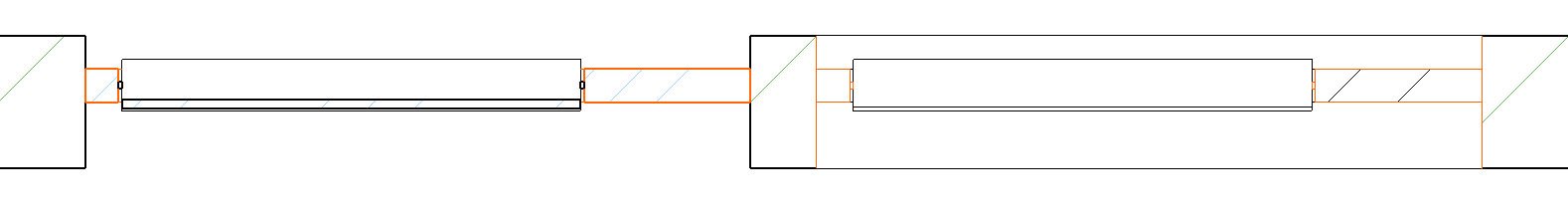
Back to fiddling with this window.
So I have managed to get the symbolic representation to show the correct lines but the lines are all shown hairline... The pens used are the same between the Projection and Symbolic views. The Wallhole created by the window tool also takes the
On a side note, I am not sure why the wall beyond in the Projected view is not shown. Is it due to the interaction with the
Ling
| AC22-29 AUS 3200 | Help Those Help You - Add a Signature |
| Self-taught, bend it till it breaks | Creating a Thread |
| Win11 | i9 10850K | 64GB | RX6600 | Win11 | 7800X3D | 32GB | RTX5070TI |
Didn't find the answer?
Check other topics in this Forum
Back to ForumRead the latest accepted solutions!
Accepted SolutionsStart a new conversation!
Suggested topics
- Archicad 29 on Apple MacBook Neo - will it work? in Installation & update
- Is Archicad really suitable for medium-scale landscape projects? in Modeling
- Horrible 2D performance on high spec laptop AMD in Installation & update
- Would like feedback regarding network speed for Bimcloud SaaS from current users in Teamwork & BIMcloud
- Choosing Between Intel Core i9-14900KF and AMD Ryzen 9 7950X for Large Archicad Projects in Installation & update
