
Turn on suggestions
Auto-suggest helps you quickly narrow down your search results by suggesting possible matches as you type.
Showing results for
EN
Turn on suggestions
Auto-suggest helps you quickly narrow down your search results by suggesting possible matches as you type.
Showing results for
Options
- Subscribe to RSS Feed
- Mark Topic as New
- Mark Topic as Read
- Pin this post for me
- Bookmark
- Subscribe to Topic
- Mute
- Printer Friendly Page
Anonymous
Not applicable
Options
- Mark as New
- Bookmark
- Subscribe
- Mute
- Subscribe to RSS Feed
- Permalink
- Report Inappropriate Content
2011-04-20
05:12 PM
- last edited on
2023-05-24
01:10 PM
by
![]() Rubia Torres
Rubia Torres
Complex Profile - Control of fill boundary lines?
2011-04-20
05:12 PM
Here is an issue that I gave up on, but perhaps someone out there
has an idea.
Here in Israel we use "wet" building procedures for many projects,
involving the erection of a CIS concrete structure which then gets
covered with a stone veneer on the outside and insulation walls on
the inside.
For many years I would model this using a Concrete slab (C 26),
on top of which would "sit" a composite wall (SMCIB 40).
Finally, the slab would get covered, as in real life, by a second
"tile" slab (TS 15), creating a 15 cm sand-filled "subfloor" where
they run the pipe works and electrical cables. Real Hi-Tech !
(continued)

6 Replies 6
Anonymous
Not applicable
Options
- Mark as New
- Bookmark
- Subscribe
- Mute
- Subscribe to RSS Feed
- Permalink
- Report Inappropriate Content
2011-04-20 05:18 PM
Anonymous
Not applicable
Options
- Mark as New
- Bookmark
- Subscribe
- Mute
- Subscribe to RSS Feed
- Permalink
- Report Inappropriate Content
2011-04-20 05:19 PM
Anonymous
Not applicable
Options
- Mark as New
- Bookmark
- Subscribe
- Mute
- Subscribe to RSS Feed
- Permalink
- Report Inappropriate Content
2011-04-20 05:27 PM
2011-04-20
05:27 PM
Then one fine day, the good folk at GS came up with the
brilliant "Complex Profile" tool. No Joking. Really.
Can this solve my problem, mom?
I set out to create a profile which would enable the composite
wall to sit flush with the concrete slab, while having the external
stone veneer cover the structures exterior without any brakes.
The profile was modeled with a "fixed" minimal hight, and much care was
given to the proper representation of the various materials constituting
the wall composite, and especially the fill boundary lines and
ending contours...
Anonymous
Not applicable
Options
- Mark as New
- Bookmark
- Subscribe
- Mute
- Subscribe to RSS Feed
- Permalink
- Report Inappropriate Content
2011-04-20 05:32 PM
2011-04-20
05:32 PM
Take notice that the Mortar and internal Insulation were set to have
an "Air Space" fill and no fill boundary. Alas, I had to choose what to do
with the enforced Edge lines, and decided I could live with a 0.2mm
thingy.
Then I hit "STORE PROFILE" -
and all those boundary lines I told AC to NOT show popped back
as mighty 0.5mm lines....
an "Air Space" fill and no fill boundary. Alas, I had to choose what to do
with the enforced Edge lines, and decided I could live with a 0.2mm
thingy.
Then I hit "STORE PROFILE" -
and all those boundary lines I told AC to NOT show popped back
as mighty 0.5mm lines....
Anonymous
Not applicable
Options
- Mark as New
- Bookmark
- Subscribe
- Mute
- Subscribe to RSS Feed
- Permalink
- Report Inappropriate Content
2011-04-20 05:42 PM
2011-04-20
05:42 PM
Understanding that AC (13..) will not allow me to do with no
fill boundaries (BTW - the composite wall tool allows one full
controll of these) -
I resorted to using 0.2mm lines for the mortar and insulation
fill boundaries.
This was done both by using the toolbar fill controls, and also by
using the nifty pet pallet tool that allows "full control" of fill
MATERIAL and EDGE LINE.
I hate to say, but AC seems to have its own mind set on this
issue, and also, NO CONTROL of FILL display order.
The attached Plan view shows a cut-line combination I never
would have thought of.
PS: Actually, the external Mortar looks OK, but the internal
Insulation got a thic line where none should be.
This behavior is quite erratic, depending what day it is...
Anonymous
Not applicable
Options
- Mark as New
- Bookmark
- Subscribe
- Mute
- Subscribe to RSS Feed
- Permalink
- Report Inappropriate Content
2011-04-20 05:49 PM
2011-04-20
05:49 PM
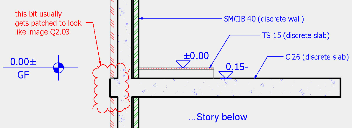
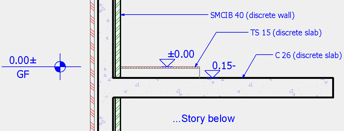
And for the final test -
Here is the same section running through the new complex profile,
the old C 26 concrete slab (they heal wonderfully), and the original
SMCIB 40 composite wall from the story below.
Comparing the two walls in section, you can see what the result should
have been VS what I got from trying to make life easier ...🙂
Also note that the Complex Profile looks different in Section
and in Plan.
Any Ideas?
(BTW, a freind told me that in Revit, Wall & Slab cores heal
in section too. But I hate the Revit interface more than I am
frustrated by AC. so, there you have it.)
Thanks -
Gil Rosenthal
Israel
Here is the same section running through the new complex profile,
the old C 26 concrete slab (they heal wonderfully), and the original
SMCIB 40 composite wall from the story below.
Comparing the two walls in section, you can see what the result should
have been VS what I got from trying to make life easier ...
Also note that the Complex Profile looks different in Section
and in Plan.
Any Ideas?
(BTW, a freind told me that in Revit, Wall & Slab cores heal
in section too. But I hate the Revit interface more than I am
frustrated by AC. so, there you have it.)
Thanks -
Gil Rosenthal
Israel
Still looking?
Suggested topics
- Extract zone position from schedule in General discussions
- Material and Surface Control in Complex Profiles in Modeling
- Can you control how profile offset modifiers change the shape of a tapered column? in Modeling
- GO of embedded layers in Project data & BIM
- How can I control window insulation strip thickness? in Libraries & objects
