
Turn on suggestions
Auto-suggest helps you quickly narrow down your search results by suggesting possible matches as you type.
Showing results for
EN
Turn on suggestions
Auto-suggest helps you quickly narrow down your search results by suggesting possible matches as you type.
Showing results for
Options
- Subscribe to RSS Feed
- Mark Topic as New
- Mark Topic as Read
- Pin this post for me
- Bookmark
- Subscribe to Topic
- Mute
- Printer Friendly Page
Tom Krowka
Enthusiast
Options
- Mark as New
- Bookmark
- Subscribe
- Mute
- Subscribe to RSS Feed
- Permalink
- Report Inappropriate Content
2005-05-06
05:53 PM
- last edited on
2023-05-23
03:36 PM
by
![]() Rubia Torres
Rubia Torres
rOOF WIZARD QUESTION
2005-05-06
05:53 PM
I guess I can select the elements and elevate them down, but it seems strange the rafters are automatically placed on top of the roof.
10 Replies 10
Rick Thompson
Advisor
Options
- Mark as New
- Bookmark
- Subscribe
- Mute
- Subscribe to RSS Feed
- Permalink
- Report Inappropriate Content
2005-05-06 06:31 PM
2005-05-06
06:31 PM
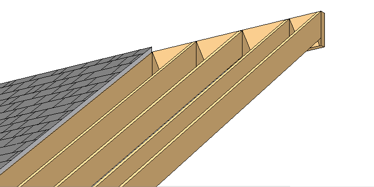
I use the wizard and place the joist on a selected roof made from a composite of air space at 5 1/2" (for 2x6's) and 1/2" sheathing above that. The joist automatically show up as they should.. see attached drawing. So, you should not need to move the place joist as they are place on the same reference line. Are you using a composite for your roof?
On this example I moved the roof over to show some of the placed joist.

On this example I moved the roof over to show some of the placed joist.
Anonymous
Not applicable
Options
- Mark as New
- Bookmark
- Subscribe
- Mute
- Subscribe to RSS Feed
- Permalink
- Report Inappropriate Content
2005-05-06 06:40 PM
Anonymous
Not applicable
Options
- Mark as New
- Bookmark
- Subscribe
- Mute
- Subscribe to RSS Feed
- Permalink
- Report Inappropriate Content
2005-05-06 07:11 PM
2005-05-06
07:11 PM
Yes, I see the Problem if you are not using the Roof Plane as the actual roof cavity Thickness, but only as the Thickness of ,say, Roof Sheathing and Roofing. In the attached Screen shot I have a Roof plane that is 1" Thick (Perpendicular dimension) I have placed the Pivot point of the Roof at 8-foot 9 3/32 inches from Story (This is a roof for a 2x8 rafter at 6:12 Pitch sitting on a 8'-1" Top plate. The Plumb height of the 7 1/4 inch rafter is 8 3/32", therefore the Height to the bottom of the roof plane is 8'-9 3/32"). This could be saved as a Favorite "Roof Ply w/ 2x8".
The Wizard sets the bottom edge of the rafter with the bottom edge of the roof. Select a created rafter with (Groups ON) and open settings and change rafter height to top plate height. (8'-1" in this case). Yes this is an extra step but no dragging.
I have not created roofs like this yet, but this is how I have been thinking of modeling them. This discussion is just me talking about how I plan to do it. Thanks for listening, not really a solution........
Graphisoft Partner
Options
- Mark as New
- Bookmark
- Subscribe
- Mute
- Subscribe to RSS Feed
- Permalink
- Report Inappropriate Content
2005-05-06 07:16 PM
2005-05-06
07:16 PM
There's no way I know of, without hacking the code somehow. This is a major problem IMHO - especially bad for log home construction.
Cheers,
Link.
(P.S. dON'T YOU hate FORGETTING THE caps LOCK? )
)
Cheers,
Link.
(P.S. dON'T YOU hate FORGETTING THE caps LOCK?
Anonymous
Not applicable
Options
- Mark as New
- Bookmark
- Subscribe
- Mute
- Subscribe to RSS Feed
- Permalink
- Report Inappropriate Content
2005-05-06 07:20 PM
2005-05-06
07:20 PM
I also do not like how the roof ply edge and Rafter edge line-up in floor plan view, but not in Section and 3d View.
The 3D can be somewhat "fake-ed in" by making the roof plane edge plumb and not perpendicular. But this is wrong in Section view. Furthermore If I was using a Composite for the roof plan with Plywood-Vapor Barrier-Roofing, the roof plan would actually need to extend past the Rafter a bit. Which means on the plan view it would have to be displayed a bit "more" than a bit. I would like the plan view not to extend at all past the rafter....
Sorry to Hi-jack this Thread with my ranting....
Anonymous
Not applicable
Options
- Mark as New
- Bookmark
- Subscribe
- Mute
- Subscribe to RSS Feed
- Permalink
- Report Inappropriate Content
2005-05-06 07:47 PM
2005-05-06
07:47 PM
Rick, do you think this has to do with what portion of the Composite that you are checking off as the Core?
Anonymous
Not applicable
Options
- Mark as New
- Bookmark
- Subscribe
- Mute
- Subscribe to RSS Feed
- Permalink
- Report Inappropriate Content
2005-05-06 08:05 PM
2005-05-06
08:05 PM
Actually Ricks Roof Composite and rafters are also lining up on the Bottom just like Non-Composites do.
BTW Rick, your screen shot shows that you have a two instances of Empty Fill1 specified as a material. One Instance it is Displayed as a Solid Fill and the other instance it is empty. How can the Same Material Display differently?
Maybe your Empty Fill1 is actually a Solid Fill with two different Pens set...
Rick Thompson
Advisor
Options
- Mark as New
- Bookmark
- Subscribe
- Mute
- Subscribe to RSS Feed
- Permalink
- Report Inappropriate Content
2005-05-06 08:06 PM
2005-05-06
08:06 PM
I would like to see the ability to have "empty fill" or "air space" actually appear that way. Then the rafters (as I have them placed above) would not be blocked from view by the empty cavity. That actually seems logical to me... but it's Friday.
The ultimate would to be able to adjust the individual parts of a composite just like you adjust the "grouped" composite. Then you could have all sorts of fun with roofs. You could easily make open rafter tails with the decking extending past the rafter ends. Just pull the cavity in from the overhang via an enhanced pet pallet. Would be even better if we could easily modify the rafter tails other than the few options we now have. I would like to take a 2x10 rafter (needed for a vaulted insulated space) and change the tail to a 2x6 profile. That take separate roofs now and then you get shingles not displaying right... extra lines in the rendering.
As it is now to have open rafter tails you would need (in my example above) to select all roofs (after creating the rafters) and replace them with a composite without the empty cavity fill and raise all the roofs... which is actually easy and fast, but a work around.
Just read your core question... I tried it and no, that does not change it.
Rick Thompson
Advisor
Options
- Mark as New
- Bookmark
- Subscribe
- Mute
- Subscribe to RSS Feed
- Permalink
- Report Inappropriate Content
2005-05-06 08:13 PM
2005-05-06
08:13 PM
Jay wrote:
BTW Rick, your screen shot shows that you have a two instances of Empty Fill1 specified as a material. One Instance it is Displayed as a Solid Fill and the other instance it is empty. How can the Same Material Display differently?
Maybe your Empty Fill1 is actually a Solid Fill with two different Pens set...
Still looking?
