Turn on suggestions
Auto-suggest helps you quickly narrow down your search results by suggesting possible matches as you type.
Showing results for
Turn on suggestions
Auto-suggest helps you quickly narrow down your search results by suggesting possible matches as you type.
Showing results for
- Graphisoft Community (INT)
- :
- Forum
- :
- Collaboration with other software
- :
- Re: Too many different volume results form the sam...
Options
- Subscribe to RSS Feed
- Mark Topic as New
- Mark Topic as Read
- Pin this post for me
- Bookmark
- Subscribe to Topic
- Mute
- Printer Friendly Page
Collaboration with other software
About model and data exchange with 3rd party solutions: Revit, Solibri, dRofus, Bluebeam, structural analysis solutions, and IFC, BCF and DXF/DWG-based exchange, etc.
Too many different volume results form the same element.
Options
- Mark as New
- Bookmark
- Subscribe
- Mute
- Subscribe to RSS Feed
- Permalink
- Report Inappropriate Content
2016-02-22 07:17 PM
2016-02-22
07:17 PM
For example, a simple foundation plan where you need to schedule the volume of the footings and stem walls.
I am not sure how ArchiCAD is making the calculations but they are not giving me the results I need.
The label with show one size, the schedule another, and dimensions even different from that-- and all for the same thing. Volumes calculated for the same thing are different if you model the footings as one monolithic slab or if they are modeled as walls.
Any tips on how to manage this for consistent and reliable results?
Model walls/footings with centerline reference lines only? Model footings/walls as Trapezoids so you can miter the corners so the intersects will not be calculated twice?
How is ArchiCAD making the volume calculation? If two footings/walls are connected at a 90 deg. corner, do they show as one volume but separate them and they show a different total volume?
I need to know how ArchiCAD is making this kind of calculation so I can find some modeling and dimensioning solution that will match/generate accurate schedules for volume.
What will generate the most accurate result? Making the calculations by hand I would use the dimension/length of the footing at the centerline of the footing. ArchiCAD is basing its calculation on how it intersects at the corners. But I don't know what the priority is for how it makes the connections. I can see it by selecting a footing/wall but not every cleanup/intersection is predictable with angled walls.
In any case, the ArchiCAD schedules I am using are not accurate and if they are consistent I am not able to predict it.

ArchiCAD 25 7000 USA - Windows 10 Pro 64x - Dell 7720 64 GB 2400MHz ECC - Xeon E3 1535M v6 4.20GHz - (2) 1TB M.2 PCIe Class 50 SSD's - 17.3" UHD IPS (3840x2160) - Nvidia Quadro P5000 16GB GDDR5 - Maxwell Studio/Render 5.2.1.49- Multilight 2 - Adobe Acrobat Pro - ArchiCAD 6 -25
Labels:
- Labels:
-
Data management
7 REPLIES 7
Options
- Mark as New
- Bookmark
- Subscribe
- Mute
- Subscribe to RSS Feed
- Permalink
- Report Inappropriate Content
2016-02-22 07:27 PM
2016-02-22
07:27 PM
... and the results for total volumes reported in the in the schedules are wrong.
If you have ever checked your foundation schedules against your hand calculations you will know what I mean.
There must be some careful coordination between the parameters being used in the schedules and the reference lines of the walls to generate a useable and reliable schedule. I don't know exactly what that is yet but I do know that my schedules are not accurate.
If you zoom in on this picture you can see the green lines that show how ArchiCAD has cleaned up the wall intersects in a way that does not produce consistent reporting of the wall lengths. They are accurate I am sure, but not generating a useful result.
ArchiCAD 25 7000 USA - Windows 10 Pro 64x - Dell 7720 64 GB 2400MHz ECC - Xeon E3 1535M v6 4.20GHz - (2) 1TB M.2 PCIe Class 50 SSD's - 17.3" UHD IPS (3840x2160) - Nvidia Quadro P5000 16GB GDDR5 - Maxwell Studio/Render 5.2.1.49- Multilight 2 - Adobe Acrobat Pro - ArchiCAD 6 -25
Options
- Mark as New
- Bookmark
- Subscribe
- Mute
- Subscribe to RSS Feed
- Permalink
- Report Inappropriate Content
2016-02-22 09:04 PM
2016-02-22
09:04 PM
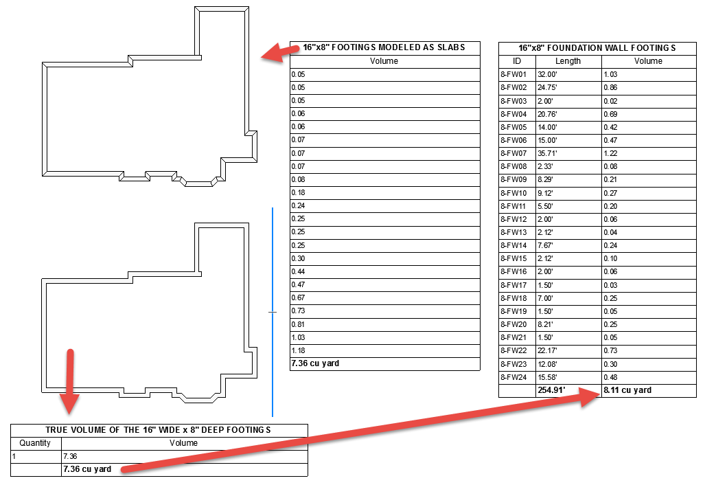
3/4 of a cubic yard difference in the true volume and the volume of the schedule for just this one type of footings. The schedule is made from the footings which were modeled as walls. The true volume is computed by hand, modeled as slabs, and as one slab.
Scheduling the footings/walls does not generate an accurate volume, the lengths shown in the labels are not the same as the lengths shown in the schedules, which are not the same as the dimensions, and it is doubtful if you can even model continuous footings as walls and expect an accurate result for volume in the schedule.
I am going to check and see it there is some way to do it accurately by moving reference lines to the center of the wall or something but I am skeptical that there will be any good solution.
The Schedules we can make in ArchiCAD always take some kind of work-around to make them work the way I want it to work.
ArchiCAD 25 7000 USA - Windows 10 Pro 64x - Dell 7720 64 GB 2400MHz ECC - Xeon E3 1535M v6 4.20GHz - (2) 1TB M.2 PCIe Class 50 SSD's - 17.3" UHD IPS (3840x2160) - Nvidia Quadro P5000 16GB GDDR5 - Maxwell Studio/Render 5.2.1.49- Multilight 2 - Adobe Acrobat Pro - ArchiCAD 6 -25
Options
- Mark as New
- Bookmark
- Subscribe
- Mute
- Subscribe to RSS Feed
- Permalink
- Report Inappropriate Content
2016-02-22 10:27 PM
2016-02-22
10:27 PM
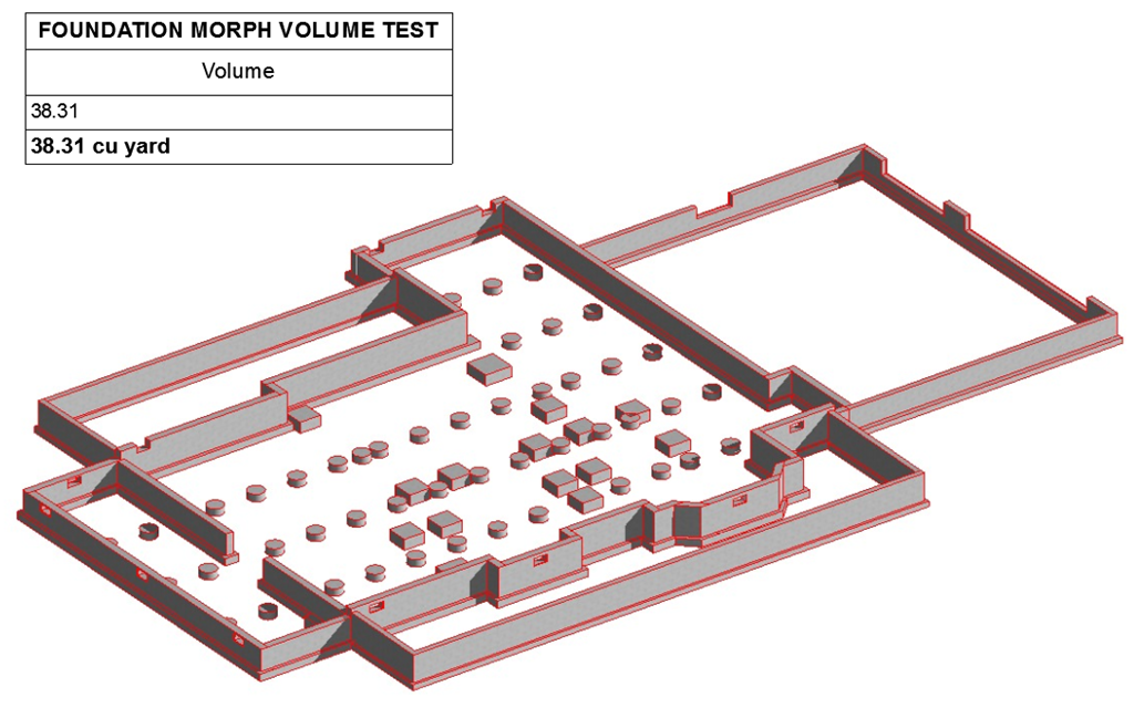
To show the difference between volume of the schedules, true and accurate volume, I converted the foundation walls and footings into an object, then converted that into a morph - then scheduled the volume of the morph.
This morph volume should be the true volume of all the footings and foundation walls. But of course it does not add up to the same volume of the other schedules.
This morph volume should be the true volume of all the footings and foundation walls. But of course it does not add up to the same volume of the other schedules.
ArchiCAD 25 7000 USA - Windows 10 Pro 64x - Dell 7720 64 GB 2400MHz ECC - Xeon E3 1535M v6 4.20GHz - (2) 1TB M.2 PCIe Class 50 SSD's - 17.3" UHD IPS (3840x2160) - Nvidia Quadro P5000 16GB GDDR5 - Maxwell Studio/Render 5.2.1.49- Multilight 2 - Adobe Acrobat Pro - ArchiCAD 6 -25
Options
- Mark as New
- Bookmark
- Subscribe
- Mute
- Subscribe to RSS Feed
- Permalink
- Report Inappropriate Content
2016-02-23 09:24 PM
2016-02-23
09:24 PM
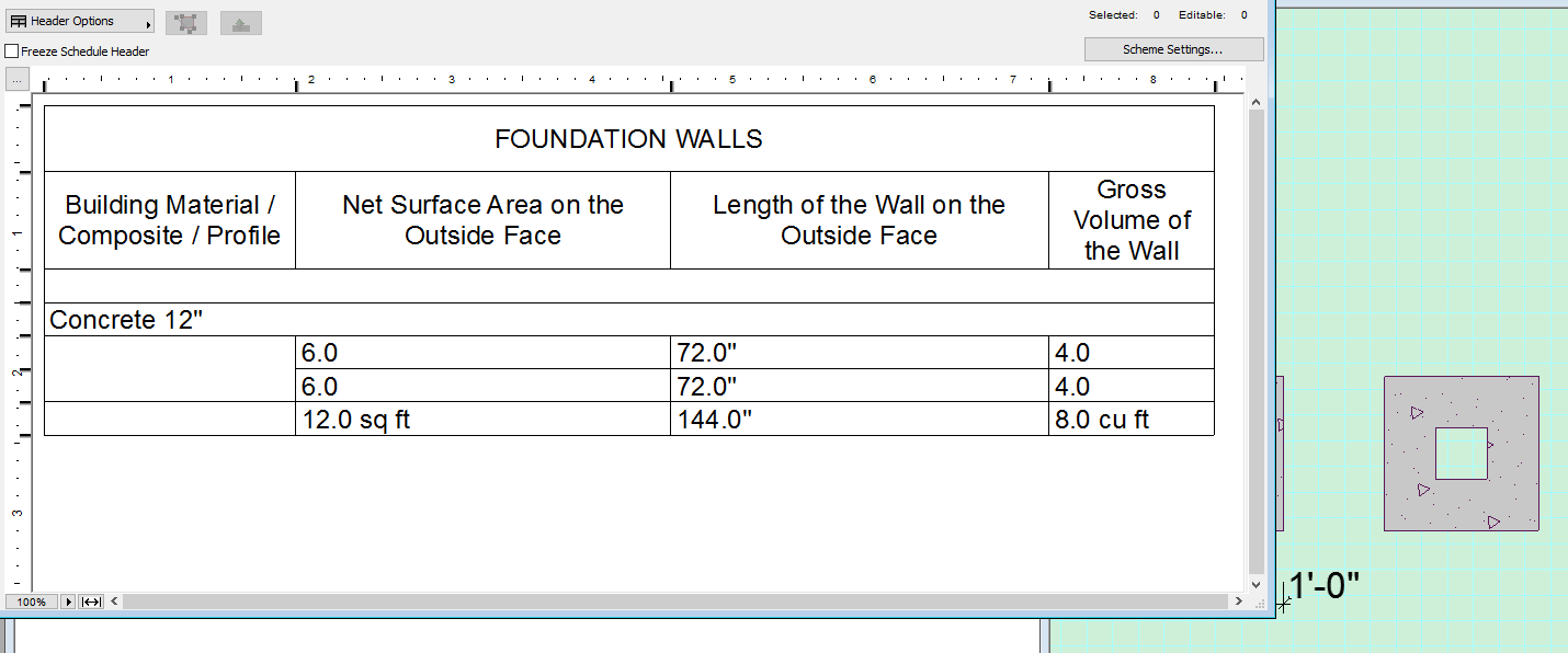
Thought I was getting odd results to so did a simple experiment. Walls are 1 foot tall and do not intersect as this is how one would calculate by hand. What it shows is the ends ore not calculated as outside face. BTW the reference line is the outside face.
David Bearss
Archicad 28/Windows 11
Alienware 17 R5
i7 2.4 GHz / 16 GB ram
Archicad 28/Windows 11
Alienware 17 R5
i7 2.4 GHz / 16 GB ram
Options
- Mark as New
- Bookmark
- Subscribe
- Mute
- Subscribe to RSS Feed
- Permalink
- Report Inappropriate Content
2016-02-23 09:26 PM
Options
- Mark as New
- Bookmark
- Subscribe
- Mute
- Subscribe to RSS Feed
- Permalink
- Report Inappropriate Content
2016-02-23 09:31 PM
2016-02-23
09:31 PM
Then the surprise; changing one wall to have reference line at center increases the outside face, length of wall on outside face and the gross volume of the wall. Not sure where this leads next but to me it all has to do with the placement of the reference line.
David Bearss
Archicad 28/Windows 11
Alienware 17 R5
i7 2.4 GHz / 16 GB ram
Archicad 28/Windows 11
Alienware 17 R5
i7 2.4 GHz / 16 GB ram
Options
- Mark as New
- Bookmark
- Subscribe
- Mute
- Subscribe to RSS Feed
- Permalink
- Report Inappropriate Content
2016-02-26 06:52 PM
2016-02-26
06:52 PM
@David Bearss
When you change the reference line the wall moved with half of wall thickness. Compare images what you attached.
Then the surprise; changing one wall to have reference line at center increases the outside face, length of wall on outside face and the gross volume of the wall. Not sure where this leads next but to me it all has to do with the placement of the reference line.Yes it changed, because the geometry has changed.
When you change the reference line the wall moved with half of wall thickness. Compare images what you attached.
i7-4770K / 16GB / GTX560 2GB / 512GB SSD / Win10 64bit
AC21 (HUN-64 bit) / Bimx Pro / Revit 2017
AC21 (HUN-64 bit) / Bimx Pro / Revit 2017
Suggested content
- Wrong text height in external drawing from dwg import in Collaboration with other software
- Element intersect coloumn & wall in Modeling
- hiding specific elements of a composite wall in Visualization
- Label – Quick Connect/Disconnect ? in Documentation
- Keynote Layers & Wrap Text issues in Documentation
Still looking?
