
Turn on suggestions
Auto-suggest helps you quickly narrow down your search results by suggesting possible matches as you type.
Showing results for
EN
Turn on suggestions
Auto-suggest helps you quickly narrow down your search results by suggesting possible matches as you type.
Showing results for
Options
- Subscribe to RSS Feed
- Mark Topic as New
- Mark Topic as Read
- Pin this post for me
- Bookmark
- Subscribe to Topic
- Mute
- Printer Friendly Page
Anonymous
Not applicable
Options
- Mark as New
- Bookmark
- Subscribe
- Mute
- Subscribe to RSS Feed
- Permalink
- Report Inappropriate Content
2008-10-10 03:52 AM
Reversed display order of lines in elevations.
2008-10-10
03:52 AM
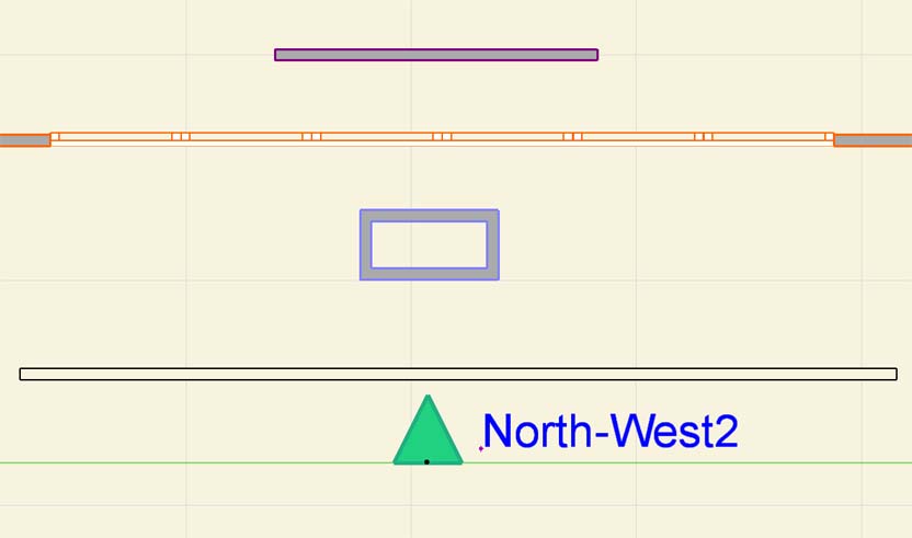
In the example elevation below, the pink wall is furthest away from the elevation line, but it visually overlaps the black horizontal lines that form the closest wall where they meet. Likewise with the other lines.
This is a seriously annoying problem, as any faded lines from the marked distant area actually overlap the bold lines at the front of a drawing! It is especially prominant with a bold ground line. Any PDFs produced from the drawing also display this error!
You can tediously get around this problem using the manual display order controls for every single element, but the whole point of modeling in 3d is that is you shouldn't have to!
I have noticed this behavior happened in AC10+11 also, so it has been around for a while. Why has it not been fixed yet? It's fundamental to the clarity of the outputted drawings -
Please confirm I'm not going mad, or I've missed some hidden setting that reverses the expected effect!

1 Reply 1
Anonymous
Not applicable
Options
- Mark as New
- Bookmark
- Subscribe
- Mute
- Subscribe to RSS Feed
- Permalink
- Report Inappropriate Content
2008-10-10 03:55 AM
Still looking?
Suggested topics
- Cover fill and object elevation relation in Documentation
- Door and window number need to differ between otherwise identical module instances in Documentation
- Display elevation tags in elevation in Documentation
- Keynotes - labels not working? in Documentation
- Archicad 29 interior elevation tool will not display glass as transparent when projected in Documentation
