Turn on suggestions
Auto-suggest helps you quickly narrow down your search results by suggesting possible matches as you type.
Showing results for
Turn on suggestions
Auto-suggest helps you quickly narrow down your search results by suggesting possible matches as you type.
Showing results for
Modeling
About Archicad's design tools, element connections, modeling concepts, etc.
- Graphisoft Community (INT)
- :
- Forum
- :
- Modeling
- :
- HOW DO SMALL FIRMS WORK?
Options
- Subscribe to RSS Feed
- Mark Topic as New
- Mark Topic as Read
- Pin this post for me
- Bookmark
- Subscribe to Topic
- Mute
- Printer Friendly Page
HOW DO SMALL FIRMS WORK?
Anonymous
Not applicable
Options
- Mark as New
- Bookmark
- Subscribe
- Mute
- Subscribe to RSS Feed
- Permalink
- Report Inappropriate Content
2009-06-24 04:36 PM
What I am trying to figure out is how most firms around our size work in ArchiCAD. Do you do all 3D, or a combination of 2D and 3D? I will explain how we work and you can tell me how far behind the times we are...
We do all our floorplans the standard way, using wall composites, library parts, etc., but we do some lines on the floorplans to show ceiling lines, wall type markers, etc. (I think this is a given). We do make sure wall heights, slab/roof heights, etc. are all correct so we can show clients a nice 3D model, so for the most part we have tight, accurate 3D models.
I think where we are "behind the times" is when we get to elevations and sections. These we do all as line drawings. We use the model as a backdrop to make sure we are on track and walls, etc are where they are supposed to be, but due to the level of detail our principals like to see, we find that making line drawings with fills are more detailed than anything else we know how to do.
I know we should look into the complex profiles/profile manager tool, I admit that we are usually too busy and the principals don't allow much time to further our knowledge in ArchiCAD, just enough time to do the project. We have explained that we can increase productivity by learning more, and now we have a few hours a week dedicated to "messing around" in the program. We don't add footings to basement walls, for example, because we just draw them in 2D in the sections.
So summarizing the questions:
1) How you do work? All 3D sections/elevation? Line?
2) What tools do you use?
3) What tools/methods would you recommend using to be more 3D (thus more efficient)?
61 REPLIES 61
Options
- Mark as New
- Bookmark
- Subscribe
- Mute
- Subscribe to RSS Feed
- Permalink
- Report Inappropriate Content
2009-10-26 08:07 PM
That is a setting within the section/elevation marker. (I never started using the dedicated "elevation" tool, and still use the section tool for both. MAybe I am missing something, but it works fine for me... but I think it works basically the same). Look on the attached image. Under "marker distance area". See the two lines in green. The upper one is where the lines go to grey. It does work very well (in my opinion) when you end up cutting a sloped roof somewhere in the middle, but only if you can cut it at the ridge, or some logical plane.
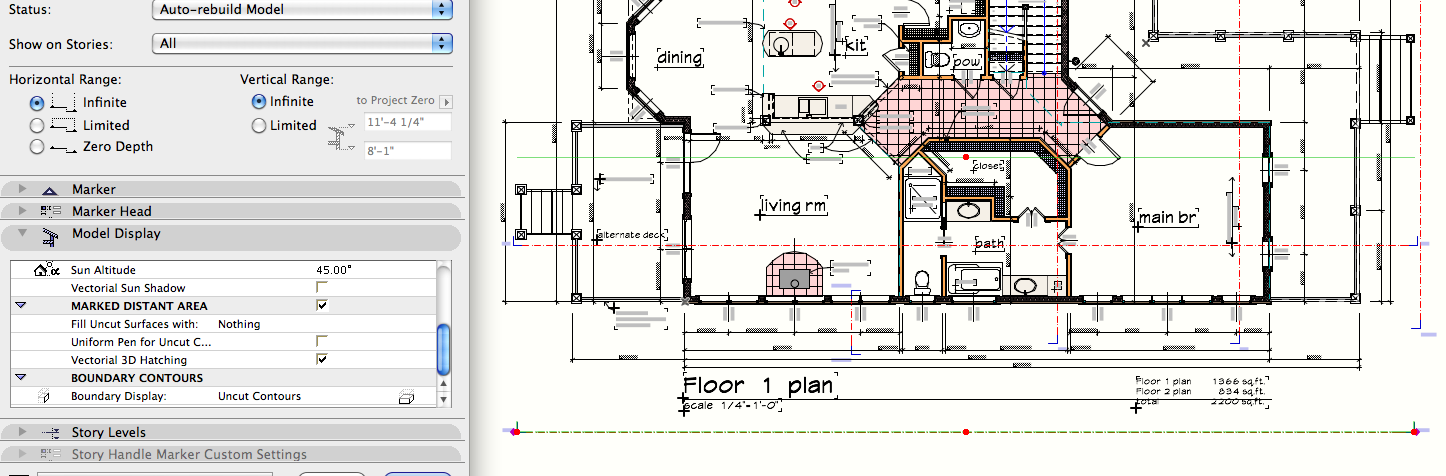
Options
- Mark as New
- Bookmark
- Subscribe
- Mute
- Subscribe to RSS Feed
- Permalink
- Report Inappropriate Content
2009-10-26 09:27 PM
Sweet, thanks for the tip Rick. I never really understood that setting before.
Doesn't quite work for every situation, but I think it is enough to add a little bit of depth to most drawings.
Cheers,
JB
Doesn't quite work for every situation, but I think it is enough to add a little bit of depth to most drawings.
Cheers,
JB
AC 21 (8002) & 22 USA
Mac OSX 10.14.5 on MacBook Pro 2.3GHz Intel i7, 16GB Ram, NVIDIA GeForce GT 750M 2GB VRAM, 500GB SSD
Mac OSX 10.14.5 on MacBook Pro 2.3GHz Intel i7, 16GB Ram, NVIDIA GeForce GT 750M 2GB VRAM, 500GB SSD
Options
- Mark as New
- Bookmark
- Subscribe
- Mute
- Subscribe to RSS Feed
- Permalink
- Report Inappropriate Content
2009-10-26 10:06 PM
Rick wrote:The primary advantage that I've found is that barring the ability to have folders to group subsets in the Project Map, it separates out the elevations from the sections This also simplifies setup of clone folders [if you happen use them].
That is a setting within the section/elevation marker. (I never started using the dedicated "elevation" tool, and still use the section tool for both. MAybe I am missing something, but it works fine for me... but I think it works basically the same).
.
Erika
Architect, Consultant
MacBook Pro Retina, 15-inch Yosemite 2.8 GHz Intel Core i7 16 GB 1600 MHz DDR3
Mac OSX 10.11.1
AC5-18
Onuma System
"Implementing Successful Building Information Modeling"
Architect, Consultant
MacBook Pro Retina, 15-inch Yosemite 2.8 GHz Intel Core i7 16 GB 1600 MHz DDR3
Mac OSX 10.11.1
AC5-18
Onuma System
"Implementing Successful Building Information Modeling"
Anonymous
Not applicable
Options
- Mark as New
- Bookmark
- Subscribe
- Mute
- Subscribe to RSS Feed
- Permalink
- Report Inappropriate Content
2009-11-05 09:22 AM
I haven't read all the posts (since the first/original), but I worked a few years for a firm that did it similar to this in the first posts: usually elevations and sections were so incredibly tedious that they bogged the projects down more than 500%. It was ridiculous. Fills were the hardest, but layer properties and priorities fixed that not long after...
With AC10 things started to become more..."capable" and realizing the 3D shift I could do, I began trying to figure out how to keep everything in the 3D model and not NEED to do 2d "touch-ups" that took 10 times longer than they should have. By AC 12 I'd figured it out, save for labels and some small technical details, and using smart layering combos and organization of objects by layer, with a few clicks I could update various options and render sections and elevations in real time in just a few seconds. Labels still took forever.
Ac 13...?
Learn the 3D. Learn it learn it learn it.
You'll cut jobs that take a month of computer work and revisions at least in half, time-wise of sitting there messing around with stuff.
I found that the resistance in AC users/peers in real-world work was not due to lack of AC's tools or abilities, but the users who didn't want to let go of some patch-work system they were used to, and worked to band-aid their usual methods to get the drawings done.
With AC 13 and the new tools, modeling everything in 3D can be done without issues to final plans- all that are needed. I use 2d just out of habit now, here and there. IF your master template is set up correctly, you're set.
Yeah learn that 3D!
Oh, and dump the other competition. I was taught on AutoCAD and have their latest (autodesk) stuff, and it's just a waste of time. I'm serious. Even Revit can't do it. I mean, it's just out of habit I think and reputation. Maybe if you're working with teamwork with people who only know it, but... ugh. I can do everything now with one program, and maybe a photo editor. I mean, even EcoTect is out of the picture, nothing can compete out there. Look at Microstaton -it's like AC 7! And people don't even KNOW that ArchiCAD is this good. I don't know about anyone else but I'm sold.
and my $0.02 on the firm- if you haven't updated your workflow, you are about 3-5 years behind where you could be, and at least 2-3 times too slow in hours and work effort that's unnecessary. At LEAST.
Options
- Mark as New
- Bookmark
- Subscribe
- Mute
- Subscribe to RSS Feed
- Permalink
- Report Inappropriate Content
2009-11-12 09:15 PM
So I am trying to do "live" sections & elevations for the first time. I have a clunky little fire repair project that is a good starter — slab on grade, roof trusses, 1-story... really simple.
Problem I'm having is how to get the "earth" fill to look right in the section.
I haven't fully modeled the earth with a mesh, though maybe that is the key? Instead I tried faking this part with a fill pattern. Fast & easy. Seems like more work than it is worth to model the whole terrain accurately when I'm really only cutting a couple of sections.
But how do I hide the footing lines beyond? If I treat this like a cover fill w/ white background, then it starts to hide thick lines where it meets the slab, footing, etc. I've tried bring to front/send to back but these don't seem to "stick" in the section, i.e. they will be jumbled up again when I rebuild from the model.
Any advice?
Cheers & TIA
AC 21 (8002) & 22 USA
Mac OSX 10.14.5 on MacBook Pro 2.3GHz Intel i7, 16GB Ram, NVIDIA GeForce GT 750M 2GB VRAM, 500GB SSD
Mac OSX 10.14.5 on MacBook Pro 2.3GHz Intel i7, 16GB Ram, NVIDIA GeForce GT 750M 2GB VRAM, 500GB SSD
Anonymous
Not applicable
Options
- Mark as New
- Bookmark
- Subscribe
- Mute
- Subscribe to RSS Feed
- Permalink
- Report Inappropriate Content
2009-11-12 10:45 PM
Hi JB,
I'd model the area of ground around the building very simply using the mesh tool (or even the slab tool if it's flat enough) using a fairly thin section pen. Use SEO to subtract away all the footings away from the mesh, then separately use SEO with upwards extrusion with the floor slabs to remove any ground above. This shouldn't take too long to do, and should update automatically if anything needs to be moved in the future.
You will have to manually add the dashed lines of the foundations behind using 2d linework. I'd do the wiggly thick ground line in 2d as well.
Options
- Mark as New
- Bookmark
- Subscribe
- Mute
- Subscribe to RSS Feed
- Permalink
- Report Inappropriate Content
2009-11-12 11:19 PM
Thanks Peter... guess I was getting lazy. That was actually pretty easy to tackle. I somehow hadn't thought of doing multiple SEOs — usually I do it all in one fell swoop.
But how do most users deal with the outlines of the mesh? See clouded areas in my new attachment. I can't for the life of me figure out how to make the mesh have no outlines in section.
JB
But how do most users deal with the outlines of the mesh? See clouded areas in my new attachment. I can't for the life of me figure out how to make the mesh have no outlines in section.
JB
AC 21 (8002) & 22 USA
Mac OSX 10.14.5 on MacBook Pro 2.3GHz Intel i7, 16GB Ram, NVIDIA GeForce GT 750M 2GB VRAM, 500GB SSD
Mac OSX 10.14.5 on MacBook Pro 2.3GHz Intel i7, 16GB Ram, NVIDIA GeForce GT 750M 2GB VRAM, 500GB SSD
Options
- Mark as New
- Bookmark
- Subscribe
- Mute
- Subscribe to RSS Feed
- Permalink
- Report Inappropriate Content
2009-11-12 11:25 PM
quick fix: in the mesh's settings change the cut line pen to white... or even better you could use a white cover fill around the edges of the mesh - that's what we typically do.
ds.
ds.
macinteract
Design Technology Managers.
All on macOS | since AC 6
Archicad Framework > Smart Template 27
Smart Tree, Transmittal and Universal Label and other smart GDL Objects
By Architects for Architects.
Design Technology Managers.
All on macOS | since AC 6
Archicad Framework > Smart Template 27
Smart Tree, Transmittal and Universal Label and other smart GDL Objects
By Architects for Architects.
Options
- Mark as New
- Bookmark
- Subscribe
- Mute
- Subscribe to RSS Feed
- Permalink
- Report Inappropriate Content
2009-11-12 11:35 PM
I find a simple fil and a heavy line at the grade to be easy and reads well. You can make the fill with a background to hide the footings, or not if you need to show them. I find both work. I have made a fill with very wide white diagonal lines to make the footings dashed. That is a easy too, but I tend to use the earth solid fill the most.
Options
- Mark as New
- Bookmark
- Subscribe
- Mute
- Subscribe to RSS Feed
- Permalink
- Report Inappropriate Content
2009-11-13 03:39 PM
jbArch wrote:ArchiCAD 13 has a new feature to address this issue, see:
But how do most users deal with the outlines of the mesh? See clouded areas in my new attachment. I can't for the life of me figure out how to make the mesh have no outlines in section.
BOUNDARY OUTLINE
(I could not quickly find this added feature on Graphisoft's web page.)
David
David Maudlin / Architect
www.davidmaudlin.com
Digital Architecture
AC27 USA • iMac 27" 4.0GHz Quad-core i7 OSX11 | 24 gb ram • MacBook Pro M3 Pro | 36 gb ram OSX14
www.davidmaudlin.com
Digital Architecture
AC27 USA • iMac 27" 4.0GHz Quad-core i7 OSX11 | 24 gb ram • MacBook Pro M3 Pro | 36 gb ram OSX14
Related articles
- Windows and doors - The biggest BIM weakness of Archicad still not taken seriously in Modeling
- Archicad options for solo business in General discussions
- SCHEDULES: Sub reports like most DBs in Documentation
- Looking for MEP and Structural firms using BIM qualified in CA - preferably Archicad in General discussions
- Quantity and Cost estimation from ArchiCAD in Collaboration with other software
Still looking?
